hi, Im currently making an Laser alarm using the 741 op-amp as a comparator.
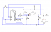
heres the circuit.

but then I came up with a problem. If I put the laser beam directly to LDR and a moving object(for example like man) moves in across the laser it will only buzz if ever he/she will stay and block the beam hitting the LDR. What I wanted to do is when an object PASS unto it, it will then trigger the alarm and start buzzing and it will only stop when someone hit the reset button. so I start searching on how to make that possible then I saw this video showing the one that I wanted.
www.youtube.com/watch?v=1k9bZklac6Q
I tried to connect my 741 dark detector to his 4017 decade counter and follow his schematic.
and the result was the buzzing wont stop even if I hit the reset button. but all works fine like what I want only the reset is not working.
help me please anyone.
thanks.
heres the circuit.
but then I came up with a problem. If I put the laser beam directly to LDR and a moving object(for example like man) moves in across the laser it will only buzz if ever he/she will stay and block the beam hitting the LDR. What I wanted to do is when an object PASS unto it, it will then trigger the alarm and start buzzing and it will only stop when someone hit the reset button. so I start searching on how to make that possible then I saw this video showing the one that I wanted.
www.youtube.com/watch?v=1k9bZklac6Q
I tried to connect my 741 dark detector to his 4017 decade counter and follow his schematic.
and the result was the buzzing wont stop even if I hit the reset button. but all works fine like what I want only the reset is not working.
help me please anyone.
thanks.