Momentary switch to power ON a circuit

Forcerouge

Jun 28, 2024
6
Joined
Jun 28, 2024
Messages
6
Hello Everyone,

I'm a noob trying to learn electronics
I'd like to make something extremely basic: a simple momentary switch in order to switch ON and OFF a small fan and a status LED.
The thing needs to be powered by a lithium battery, so with voltages ranging from 4.2V to 3V or so.

I have a small charging system (TP4056) and a small BMS system (DW01A with a 8205A dual mosfet) on this board. These work fine, the battery charges and status LEDs work ok (red when charging, green once charged).

When I press the momentary switch, I want the current coming from the battery to power a small 5V fan and a blue LED to indicate that the thing is working.
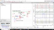
In order to do that, I searched the internet and found this circuit: switch circuit in Falstad simulator:
1719590031984.png

It worked great on the simulator, so I assumed it was fine and I designed a small PCB board:

1719589392201.png


Problem is it doesn't seem to work at all after I made the board, when I press the button nothing happens.
I tried switching C4 to 10uF since it seemed to work better in the simulator, but it didn't make any difference.

Do you guys have any idea what could be going on here?
Thanks a lot in advance for your answers
 
Last edited:

danadak

Feb 19, 2021
1,062
Joined
Feb 19, 2021
Messages
1,062
Just for future reference you can do this in mBlock on a small micro,
ATTINY85, with more accurate timing and flexibility of functionality,
and debouce the switch as well : (I think this would work)
1719605935663.png

mBlock takes your block program and generates Arduino code and can either program directly a low cost board
like the Nano or use the Nano to program the 8 pin dip type of part. Lots of fun.

1719605965563.png


Regards, Dana.
 

Attachments

  • Fan and LED Time Delay.zip
    55.5 KB · Views: 0

Delta Prime

Jul 29, 2020
2,987
Joined
Jul 29, 2020
Messages
2,987
trying to learn electronics
I'd like to make something extremely basic: a simple momentary switch in order to switch ON and OFF a small fan and a status LED.
The thing needs to be powered by a lithium battery, so with voltages ranging from 4.2V to 3V or so.
It is not extremely basic.
You have 4.2Vdc maximum lithium ion battery
3.7Vdc nominal. Trying to power a 5Vdc fan?
You see what I mean.... :)
I want the current coming from the battery to power a small 5V fan and a blue LED to indicate that the thing is working.
More reading is necessary. Good luck to you.
 
Last edited:

Delta Prime

Jul 29, 2020
2,987
Joined
Jul 29, 2020
Messages
2,987
Don't think so.. in either case you're going to need a DC to DC converter. A boost converter. Advantages they come in all flavors to increase boost voltage or decrease buck voltage or both a boost buck converter.
photo_1719629713805.png
 
Last edited:

Forcerouge

Jun 28, 2024
6
Joined
Jun 28, 2024
Messages
6
It is not extremely basic.
You have 4.2Vdc maximum lithium ion battery
3.7Vdc nominal. Trying to power a 5Vdc fan?
You see what I mean....
Not really sure what you mean actually. The 5V fan still works just fine at 3V, it only spins slower, which does not matter for this particular application.
The problem is that it just doesn't turn on at all, even with the battery fully charged.
But this is actually my second version of this circuit. The first one turned on and everything was working perfectly... except it wouldn't turn off when pressing the button again.
 
Last edited:

Forcerouge

Jun 28, 2024
6
Joined
Jun 28, 2024
Messages
6
Just for future reference you can do this in mBlock on a small micro,
ATTINY85, with more accurate timing and flexibility of functionality,
and debouce the switch as well : (I think this would work)
View attachment 64022

mBlock takes your block program and generates Arduino code and can either program directly a low cost board
like the Nano or use the Nano to program the 8 pin dip type of part. Lots of fun.


Regards, Dana.
Thanks, I'm certain this would work and this is a valid solution, but in my opinion using a microcontroller to do this is a bit overkill. I know how to use an arduino so I could even program in the standard arduino IDE if needed. But I appreciate the suggestion, thanks.

My goal is to learn how to make this work in a more "professional" way, just using transistors and passive components.
I think I understood how it is supposed to work after spending a lot of time experimenting with it on Falstad simulator and I'm fairly sure it should work in real life, but I obviously made a mistake somewhere between the simulator and manufacturing and I just can't find it.

I do not need a voltage converter. I know this for sure because I'm actually trying to replicate a commercially available product in order to improve its function to suit a particular need I have in my homeshop. And this product doesn't have any voltage converter, it just takes raw battery power, sends it to the fan through a similar power latching system using a momentary switch.
 

Forcerouge

Jun 28, 2024
6
Joined
Jun 28, 2024
Messages
6
Two below...one from talkingelectronics ........ https://www.talkingelectronics.com/te_interactive_index.html
look for "555 toggle a relay"

....and then there is this video off youtube....
Yes I've seen most videos on the subject already, but this particular one is using a completely different system. I'd like it to work with the components I already have, I guess for an electronics engineer it should be relatively easy as these momentary push button switches are pretty much everywhere around us but for me it's a bit like dark magic.
 

danadak

Feb 19, 2021
1,062
Joined
Feb 19, 2021
Messages
1,062
Thanks, I'm certain this would work and this is a valid solution, but in my opinion using a microcontroller to do this is a bit overkill. I know how to use an arduino so I could even program in the standard arduino IDE if needed. But I appreciate the suggestion, thanks.

My goal is to learn how to make this work in a more "professional" way, just using transistors and passive components.
I think I understood how it is supposed to work after spending a lot of time experimenting with it on Falstad simulator and I'm fairly sure it should work in real life, but I obviously made a mistake somewhere between the simulator and manufacturing and I just can't find it.

I do not need a voltage converter. I know this for sure because I'm actually trying to replicate a commercially available product in order to improve its function to suit a particular need I have in my homeshop. And this product doesn't have any voltage converter, it just takes raw battery power, sends it to the fan through a similar power latching system using a momentary switch.

Of course low end micros these days are like OpAmps and Regulators, simple, low cost,
and so much more flexible. And generally save board area, componefornt count, and
more reliable due to lower component count. Youtube has a series of videos on 3 - 20 cent
micros, quite capable actually, not great but adequate support.

Some higher end micros nowadays have the following resources (multiple copies in most cases)
in them, for the higher end more complex designs :

1719658335326.png

But I appreciate discrete designs, can be lots of fun to explore.
 

danadak

Feb 19, 2021
1,062
Joined
Feb 19, 2021
Messages
1,062
Something like this ?

1719679614325.png

Button goes across cap.


Regards, Dana.
 

danadak

Feb 19, 2021
1,062
Joined
Feb 19, 2021
Messages
1,062
A little better sim :

1719745405989.png


The initial phase is power up, then at 3 sec a switch pulse on.

Regards, Dana.
 

Attachments

  • 1719745298395.png
    1719745298395.png
    173.6 KB · Views: 0

Bluejets

Oct 5, 2014
7,374
Joined
Oct 5, 2014
Messages
7,374
Don't think so.. in either case you're going to need a DC to DC converter.
Cmos 555 go much lower supply voltage....check it out first, then comment.
.............or as mechanic says, put brain in gear before opening gob.
 

Delta Prime

Jul 29, 2020
2,987
Joined
Jul 29, 2020
Messages
2,987
@Bluejets
f ou even mentioned a 7555 anywhere it would have been helpful... I was addressing the thread starter. Now leave me alone. You're not qualified to address me. ..
"Vescere bracis meis" -Delta Prime
:p
 
Last edited:

Harald Kapp

Moderator
Moderator
Nov 17, 2011
14,270
Joined
Nov 17, 2011
Messages
14,270
when I press the button nothing happens.
Have you checked the correct placement/rotation of the pushbutton?

Do you have (measured) battery voltage across C5? Make sure the battery protection circuit U3 connects BAT- to B-
 

danadak

Feb 19, 2021
1,062
Joined
Feb 19, 2021
Messages
1,062
The LMC555 timer does operate down to 1.5V, but key issue is getting
power MOSFET to turn on at real low Vgs. Circuit in post #14 sims down
to 3V, but has annoying power on transient to load and for very long
delays not sharp turn off.

@OP, what on time do you want ?


Regards, Dana.
 
Top