Serious Help Needed - Pad Lifted off

Tron788

Mar 20, 2014
14
Joined
Mar 20, 2014
Messages
14
Hi all, I really could use your expert opinion with this one.
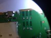
This PCB multi-layered its from an air-card (mobile hotspot) and the sim slot became damaged and it needed replacing. As you can see from the image attached two solder pads where accidentally detached during removal of the SIM card slot. So I need your expert opinion on this case. 1st) is this repairable...? 2nd) What's your suggestion on technique\method would be used to find and rebuild these pads....?

Thanks for your suggestions, look forward to you ideas.
 

Attachments

  • image.jpg
    image.jpg
    115.1 KB · Views: 177

mursal

Dec 13, 2013
75
Joined
Dec 13, 2013
Messages
75
We have had good results with superglue. The joint will be dry so you will have to ensure you have electrical connection before the glue hardens. Consider using it to attach the pad to the socket, on the damaged pins, to stop overheating. Hopefully the other pads will give enough support. Double check continuity through all joints before inserting card.
 

Tron788

Mar 20, 2014
14
Joined
Mar 20, 2014
Messages
14
Hi, humm glue....?
The problem is that the pads shown are missing connection or any sign were to connect to.
 

davenn

Moderator
Sep 5, 2009
14,470
Joined
Sep 5, 2009
Messages
14,470
I dont see those pads connecting to anything ... other tracks
if they were connecting to something on another layer therre would be via holes
and there are none of those ---- it ;looks like a dummy mount

why were you removing the SIM holder ?

and no gluie isnt going to solve this problem

Dave
 

Tron788

Mar 20, 2014
14
Joined
Mar 20, 2014
Messages
14
G'day Davenn, The reason for removing the SIM card slot was because the internals became damage and weren't working at all. I did find a replacement SIM card slot though.
I try and get a diagram of the SIM card slot to decipher what the contacts of the SIM card slot do what. Just in case you're right about Dummy contacts,,,thanks for your assistance.

I'll come back with some update details.
 

Attachments

  • image.jpg
    image.jpg
    50.1 KB · Views: 133

Tron788

Mar 20, 2014
14
Joined
Mar 20, 2014
Messages
14
Trouble

Ok from web research, this is what I've been able to determine;
A Sim Card have six pads that also corresponds to the six SIM connectors pins, but only five have total connection on the entire layout.
SIM DATA - this is a digital data that being stored on a SIM memory.
SIM Clock - this is a clock frequency signal that being synchronize to the digital data to create data signal in order transfer or sends and receive data information.
SIM Reset - this is also a frequency signal that triggers or reset all synchronization process.
VSIM B+ Supply Voltage- This a power supply voltage used to activated the SIM circuit.
SIM Ground - a ground line voltage.
The other one is not connected.
So what's been observed is from the circuit diagram and the way the sim alines with sim slot is that VSIM & GND pads have been detached....:(

Can any one confirm this. Any additional suggestion to recover VSIM pad would be much appreciated.
 

Attachments

  • SIM+CARD+block+diagram.jpg
    SIM+CARD+block+diagram.jpg
    24.8 KB · Views: 102
Last edited:

davenn

Moderator
Sep 5, 2009
14,470
Joined
Sep 5, 2009
Messages
14,470
please answer ..... has the SIM holder ever worked on this unit ??
that is .... have you ever used it ?

I still see no obvious connection of any of those 6 pins to any other part of the circuitry
and unless you can confirm/prove otherwise, it still looks like the SIM is an unused/unuseable feature on that version of the board

Dave
 

Tron788

Mar 20, 2014
14
Joined
Mar 20, 2014
Messages
14
Yes the device worked, BUT has only semi-worked since ownership. Sim card not recognised since I've owned it. The original owner assures me it worked from purchase.
But from inspection sim card slot holder was accuatly damaged (contact legs had broken) reason no sim recognised, hence the need for replacing sim slot holder.

I'm now going to attempt to attach sim card slot holder replacement to only the remaining contact pads available, as suggested to determine if this will be suffice to do the trick. :eek: I'll be back.
 

Tron788

Mar 20, 2014
14
Joined
Mar 20, 2014
Messages
14
Found them

Update - from further inspection and cleaning of the lifted pads areas. I'll confirm that I have exposed two micro pins on each pad of the pads for contact attachment.

So my question comes down to technique in attaching solder to these pins to build pads please forward me correct methods. Eg equipment, temp, pin exposure, pad rebuild ect.

There must be different variation people use....?
 

davenn

Moderator
Sep 5, 2009
14,470
Joined
Sep 5, 2009
Messages
14,470
Sim card not recognised since I've owned it.

that's the important bit

The original owner assures me it worked from purchase.

and sellers make all sorts of claims ;(


I'll confirm that I have exposed two micro pins on each pad of the pads for contact attachment.

I don't even know what that means ??

clean the solder off the other 4 pads with solder wick and show me a sharp well lit and closeup pic of the contacts on the PCB
I want to know if there are any through holes on any of the pads

going by the 2 pads lifted off there are no through holes ( vias as they are called) which indicates those 2 pads DIDNT connect to anything else

I still believe the SIM never worked and couldn't work going by what I can currently see

So my question comes down to technique in attaching solder to these pins to build pads please forward me correct methods.

This is what I have been trying to explain to you .... there is NOTHING to solder to. There is NOTHING below where those pads were

Dave
 
Last edited:

(*steve*)

¡sǝpodᴉʇuɐ ǝɥʇ ɹɐǝɥd
Moderator
Jan 21, 2010
25,510
Joined
Jan 21, 2010
Messages
25,510
Mostly we melt the solder before tearing components from the board.

You may be able to repair it, but if the via connects to an internal layer on the board you may not.

It is highly unlikely that the socket was the original fault -- although it's clearly one now.

Hold the board up to the light and see if you can make out traces on the other side through blank areas of the board. If not, there may be inner layers. You can sometimes see them if you know what to look for. Look at the edges of the board, sometimes there are clues there too.

If the board is just double sided and the connections go through to the other side, you can try either placing a very fine wire in the via, or (more risk) drilling out the via a little so you can place a fine wire in it and solder it to the track on the other side. If it's a multi-layer board, drilling the via will be certain death to the board.
 
Top