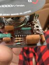
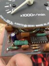
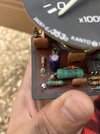
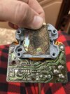
Hello all I am new to the forum and to small electronics in general so sorry if this is in the wrong spot or if call things the wrong name. Anyways I’ve been trying to diagnose this tachometer from a project truck of mine and I will post detailed pictures of it below. Anyways, it obviously dosent work I’ve noticed what I believe is a 14pin high bridge getting extremely hot and I believe that is is fried, as well as what I believe is a resistor that is red in color with a single yellow band that also gets extremely hot. Problem is I can’t find any schematics for this tach, can’t find any matching bridges, and I’m not sure what the ohm rating on the resistor is with it being a single band. Also all of the sharpie on the back was not put there by me it was there before so theirs a possibility someone may have messed with it. I’m not for certain where to start. Please help.
")

