THRUSTMASTER T300 HELP!

LDF_TINCHO

Mar 29, 2021
3
Joined
Mar 29, 2021
Messages
3
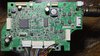
Hello, my problem with the thrustmaster is that a button on the PCB has been electronically pressed, it is button 1 corresponding to the left gear.

In the photo of the board there are two jst connectors that correspond to the gear buttons, one of them, (left pad conector,), shows continuity, I don't know where the problem is.
How could I repair or cancel this order?
 

Attachments

  • thrustmaster t 300 pcb :a.jpeg
    thrustmaster t 300 pcb :a.jpeg
    342.8 KB · Views: 93

Harald Kapp

Moderator
Moderator
Nov 17, 2011
14,097
Joined
Nov 17, 2011
Messages
14,097
Show us a closer look. Show us also the underside of the PCB. Look for stray solder that may have created a short circuit. Look on top and bottom of the PCB. Sometimes pearls of solder from the manufacturing process that have not been cleaned away may stick between traces or solder points.
The issue may, however, be an internal one of the controller circuit. In that case you'd be lost.
 

anylap23

Dec 9, 2021
2
Joined
Dec 9, 2021
Messages
2
Hi!!
Did you find something about?.

I have the same issue but R3 button, where I soldered a parallel switch for hand brake.
First thing I did was unplug the L3/R3 pcb. Same result......R3 stuck.
I had try with a parallel switch pressing to see if it get unlocked, but doesn´t work.
Also tried to follow the circuit with a multimeter, but i get lose in some point without detecting any shortcircuit because i have no schematic diagram of te motherboard.
I think that issue comes from the processor, but i´m not sure.
 

LDF_TINCHO

Mar 29, 2021
3
Joined
Mar 29, 2021
Messages
3
In my case I solved it by looking for a bit of current in the connector that goes to the steering wheel I think, and inject the positive in the pin of the button that is stuck, on the PCB, the voltage that must be 2.6 I think
 

73's de Edd

Aug 21, 2015
3,728
Joined
Aug 21, 2015
Messages
3,728
thinking along the same lines as . . . . . LDF_TINCHO . . . . ., go to the other paddle / gear that has no problem and compare its voltage with out switch activation and then with it activated .
The do the same test with your PROBLEM unit, but expecting no change there . . . if so, then unplug its two pin connector to simulate a paddle/gear DE ACTIVATION. Then . . . . . are the pairs of voltages the same, between units ? That differentiates between a circuit problem and the actual switch itself . . .or somewhere in its routing.
 

redzoome

Feb 23, 2025
2
Joined
Feb 23, 2025
Messages
2
Hello guys.
I understand that is very old thread, but, i have same problem, like anylap23, with stuck L3 button, after I soldered a parallel switch for hand brake. Nothing visible issues, some kind of programming or processor error.
Glad to any help)
 

Harald Kapp

Moderator
Moderator
Nov 17, 2011
14,097
Joined
Nov 17, 2011
Messages
14,097
If the button is stuck in the "closed" position, a parallel switch will not help as it can not open the circuit that is closed by the other button. If this is the case, you need to remove the stuck button.
 

redzoome

Feb 23, 2025
2
Joined
Feb 23, 2025
Messages
2
If the button is stuck in the "closed" position, a parallel switch will not help as it can not open the circuit that is closed by the other button. If this is the case, you need to remove the stuck button.
Circle is not closed by other button. Citrcle closed in some kind of program or processor level. I did was unplug the L3/R3 pcb. Same result......L3 stuck.
 

Westheightstp

Jul 11, 2025
2
Joined
Jul 11, 2025
Messages
2
Hi!!
Did you find something about?.

I have the same issue but R3 button, where I soldered a parallel switch for hand brake.
First thing I did was unplug the L3/R3 pcb. Same result......R3 stuck.
I had try with a parallel switch pressing to see if it get unlocked, but doesn´t work.
Also tried to follow the circuit with a multimeter, but i get lose in some point without detecting any shortcircuit because i have no schematic diagram of te motherboard.
I think that issue comes from the processor, but i´m not sure.
Hey mate i know this post is old but did you manage to fix the issue? I did the same with mine. Soldered in wires in the correct spots and plugged back in and the R3 registers as ON even with the R3/L3 pcb plug disconnected
 
Top