What N-Mosfet to control a small DC motor

beatlerat

Aug 26, 2024
5
Joined
Aug 26, 2024
Messages
5
Hi,
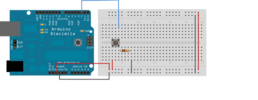
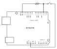
I am completely in the dark on this. What N-Mosfet (logic level?) would I use to control this motor through an arduino nano using a simple fade in fade out LED type circuit to control the mosfet.
Thanks,
If you need additional info, I will try to supply it.
 

Delta Prime

Jul 29, 2020
2,987
Joined
Jul 29, 2020
Messages
2,987
To be blunt; would you like for me to pick out the N-Channel MOSFET for you?
Arduinos use logic level signals of 3.3 or 5 volts at around 20 mA, but to drive power MOSFETs effectively, you need about 12 volts and enough current to drive them quickly.
If you want to use an N-channel MOSFET with an Arduino, you can connect the ground pin to the MOSFET's source terminal. Then, you can turn the MOSFET on and off from a digital output pin. You can also wire it up to be off by default by adding a approx 1 mega ohm pulldown resistor from the gate terminal to the source.
 

beatlerat

Aug 26, 2024
5
Joined
Aug 26, 2024
Messages
5
To be blunt; would you like for me to pick out the N-Channel MOSFET for you?
Arduinos use logic level signals of 3.3 or 5 volts at around 20 mA, but to drive power MOSFETs effectively, you need about 12 volts and enough current to drive them quickly.
If you want to use an N-channel MOSFET with an Arduino, you can connect the ground pin to the MOSFET's source terminal. Then, you can turn the MOSFET on and off from a digital output pin. You can also wire it up to be off by default by adding a approx 1 mega ohm pulldown resistor from the gate terminal to the source.
That is exactly how I planned on doing it. I have chosen this mosfet (IRLB8721), and if this will do what I am looking for, then perfect. If not, please let me know.
Thanks.
 

Minder

Apr 24, 2015
3,561
Joined
Apr 24, 2015
Messages
3,561
What current & Voltage is required to drive the motor
Use a (5v) logic level gate Mosfet.
STP40NF10Lrated at 100v max, 40A ,There is also IRLZ34NPBF.
 
Last edited:

Delta Prime

Jul 29, 2020
2,987
Joined
Jul 29, 2020
Messages
2,987
Motor Rated Voltage is 3 volts to 9 Volts
Moror rated current is 0.12 Amps to
0.19 Amps. :)

That is exactly how I planned on doing it.

For default OFF
Replace the 1 Mega Ohm pulldown resistor (my mistake) with 10k Ohm resistor.
Your choice of N-Channel MOSFET
Will work .Your good to go...
 

Bluejets

Oct 5, 2014
7,374
Joined
Oct 5, 2014
Messages
7,374
I usually use a common IRLZ44N but yours should work ok.
A gate resistor of 220 ohm to the Arduino and a 10k to ground.
Separate supply to to motor will give some noise isolation.
When choosing switching device, remember motors may require up to 6 times full load current instantaneously.
 

Harald Kapp

Moderator
Moderator
Nov 17, 2011
14,270
Joined
Nov 17, 2011
Messages
14,270
The IRLB8721 is more than enough for this motor:

motor: 0.2 A
MOSFET: >30 A @VGS>=4 V
Do not forget the freewheeling diode across the motor to protect the MOSFET from voltage spikes.


Note: The MOSFET has an input capacitance of ~ 1 nF. The current limit of 20 mA per Arduino output pin means that the rise time of VGS is on the order of 300 ns. This is comparatively slow and may cause excessive power dissipation in the MOSFET. Consider using an additional MOSFET driver, e.g. LTC7004 if the MOSFET gets too hot.
 

Minder

Apr 24, 2015
3,561
Joined
Apr 24, 2015
Messages
3,561
You may even get away with the 2700 at that current 200ma, 500ma pulsed (PWM) .
 

beatlerat

Aug 26, 2024
5
Joined
Aug 26, 2024
Messages
5
Thanks for all of your replies. The IRLB8721 did not work, but it may have been an issue on my part. What did work was this.
So part of the code is working, but the part that controls the button is not.
The plan was to check the status of a momentary button (pin2), and if it is low (or high), do nothing. If there is a change in the button status (pushed), then run a motor (pin9) and after completing the the ramps and delay, return to the "check the status", and wait until the the status changes and run the loop again. I assumed the "check the status" is inside the loop.
I was using a 10k pull down resistor, but it is not working.
I don't care if I start high or low, I can configure it either way, but it would be nice if I could use the onboard pullup resistor and go that route. The code is included.
 

Attachments

  • area51motor.ino
    2 KB · Views: 3

Bluejets

Oct 5, 2014
7,374
Joined
Oct 5, 2014
Messages
7,374
Thanks for all of your replies.
When you include any code, best to place inside code brackets.
That way others can see what the code includes, without having to open in Arduino IDE or other program to view.

Also include a circuit diagram ( NOT fritzing), same reason.
Show what worked and what did not work so others can comment on where you went wrong.
 

beatlerat

Aug 26, 2024
5
Joined
Aug 26, 2024
Messages
5
Sorry, New to the forum.
Not sure how to do this.
C:
*/
// constants won't change. They're used here to set pin numbers:
const int PushButton = 2;  // the number of the pushbutton pin
const int MOTORPin = 9;    // MOTOR connected to digital pin 9
// variables will change:
int buttonState = 0;  // variable for reading the pushbutton status

void setup() {
   // initialize the pushbutton pin as an input:
  pinMode(PushButton, INPUT);
 
}
void loop() {
  // read the state of the pushbutton value:
  buttonState = digitalRead(PushButton);
  // check if the pushbutton is pressed. If it is, the buttonState is HIGH:
  if (buttonState == HIGH) {
    // turn MOTOR on:
    digitalWrite(pinMode, HIGH);
  } else {
    // turn motor off:
    digitalWrite(pinMode, LOW);
  }
 // fade in from min to max in increments of 3 points:
      for (int fadeValue = 0 ; fadeValue <= 200; fadeValue += 3) {
        // sets the value (range from 0 to 200):
        analogWrite(MOTORPin, fadeValue);
        // wait for 60 milliseconds to see the dimming effect
        delay(60);
      }
    
      delay(8000);   // wait 8 seconds
    
      // fade out from max to min in increments of 3 points:
      for (int fadeValue = 200 ; fadeValue >= 0; fadeValue -= 3) {
        // sets the value (range from 0 to 200):
        analogWrite(MOTORPin, fadeValue);
        // wait for 60 milliseconds to see the dimming effect
        delay(60);
    
      }
      delay(10000);   // wait 10 seconds
    }
[Mod edit: placed into code box]
 

Attachments

  • layout.png
    layout.png
    40.2 KB · Views: 3
  • schematic.png
    schematic.png
    25.7 KB · Views: 2
Last edited by a moderator:

danadak

Feb 19, 2021
1,062
Joined
Feb 19, 2021
Messages
1,062
Use the code tags and post code in that popup window.

Click on </> in the 3 vertical dot menu to get to the popup window.

It look like some of your code outside main loop....?

You also dont debounce your button press, should bounce it in, then out, then act on it.

If you want to detect button + (or - for that matter) edge you need a variable to hold last
read so that current read pressed can be detected and compared, then bounce it in and act on
it. If button pulls pin up that gives you + edge.


Regards, Dana.
 
Last edited:

Martaine2005

May 12, 2015
5,276
Joined
May 12, 2015
Messages
5,276
Dana, I’ve learned so much from your posts. I never touched a micro before it came apparently easily. Still not easy but easier!.
 

beatlerat

Aug 26, 2024
5
Joined
Aug 26, 2024
Messages
5
I came in here knowing nothing about code and so far I'd say you all are more concerned with my posts being in a certain format than helping me with my issue. I guess this forum is the wrong place to ask for help.
I'll look elsewhere and sorry I wasted your time.
 

Martaine2005

May 12, 2015
5,276
Joined
May 12, 2015
Messages
5,276
I came in here knowing nothing about code and so far I'd say you all are more concerned with my posts being in a certain format than helping me with my issue. I guess this forum is the wrong place to ask for help.
I'll look elsewhere and sorry I wasted your time.
Your posts are relevant for coding platforms. This forum is for electronics. However, there are some very decent coders/programmers on here too.
If you took the time to post your code, you should have noticed a code box!. Dang, these people that slag off a site because’they’ can’t use it:)
 

danadak

Feb 19, 2021
1,062
Joined
Feb 19, 2021
Messages
1,062
I think this will work -

1725146267754.png

Coded with mBlock, it takes your block configs and values and converts to
Arduino code. I use this for one off simple stuff, otherwise do it in C.

Here is the code it produced :

Code:
// generated by mBlock5 for <your product>
// codes make you happy

#include <Arduino.h>
#include <Wire.h>
#include <SoftwareSerial.h>

float fadeincrement = 0;
float fadeval = 0;
float fademaxval = 0;
float fadewait = 0;

void fademotoroff(){
  fadeval = fademaxval;
  while(!(fadeval < 1))
  {
    _loop();
    fadeval += -1 * fadeincrement;
    chknegativeval();
    analogWrite(9,fadeval);
    _delay(float(fadewait));

  }

}
void fademotoron(){
  fadeval = 0;
  while(!(fadeval > fademaxval))
  {
    _loop();
    fadeval += fadeincrement;
    analogWrite(9,fadeval);
    _delay(float(fadewait));

  }

}
void debounce_N(double pinnum){
  // Detect + edge button, then loop until its released
  while(!(digitalRead(2) == 1.000000))
  {
    _loop();
    _delay(0.1);

  }
  while(!(digitalRead(2) == 0.000000))
  {
    _loop();
    _delay(0.1);

  }

}
void chknegativeval(){
  if(fadeval < 0){
    fadeval = 0;

  }

}

void _delay(float seconds) {
  long endTime = millis() + seconds * 1000;
  while(millis() < endTime) _loop();
}

void setup() {
  pinMode(9,OUTPUT);
  pinMode(2,INPUT);
  // Motor Off
  analogWrite(9,0);
  fadeincrement = 3;
  fadeincrement = 200;
  fadewait = 0.06;
  while(1) {
      debounce_N(1);
      fademotoron();
      _delay(8);
      fademotoroff();
      _delay(10);

      _loop();
  }

}

void _loop() {
}

void loop() {
  _loop();
}

Regards, Dana.
 
Last edited:

danadak

Feb 19, 2021
1,062
Joined
Feb 19, 2021
Messages
1,062
Dana, I’ve learned so much from your posts. I never touched a micro before it came apparently easily. Still not easy but easier!.
I figure I know ~ .001% of the worlds Micro knowledge, striving to hit .002%. But clock is
ticking on my old fat ass......:)
 

Delta Prime

Jul 29, 2020
2,987
Joined
Jul 29, 2020
Messages
2,987
I figure I know ~ .001% of the worlds Micro knowledge, striving to hit .002%
Knowledge is limitted in the individual human brain. You pass on knowledge to others.
I don't need to know everything.
I need to know the one who Knows.
For contributing. Thank you Sir.:)
 

danadak

Feb 19, 2021
1,062
Joined
Feb 19, 2021
Messages
1,062
@beatlerat

Attached the mBlock project in case you want to look at it. Just download
mBlock, its free, and open it.


Regards, Dana.
 

Attachments

  • FadeMotor.zip
    56 KB · Views: 0
Top