

Temperature Controlled FAN using ATtiny10
- Emmanuel Odunlade
- https://twitter.com/emmaodunlade
- emmaodunlade@gmail.com
- 3.998 Views
- medium
- Tested
- 0 Likes

The electrons movement in electronic components lead to the generation of heat which when beyond certain thresholds, prevents some components from functioning properly and in others could lead to a catastrophic breakdown. For this reason, the topics of ventilation, overheating, and cooling are important discussions in the design of any device. Several cooling solutions, including popular ones like; the use of aluminum heat sinks, and fans/heat extractor can be adopted for a project but the ultimate choice usually depends on the amount of heat produced and the maximum level the components can withstand. Heat extractors/fans are used in devices like Laptop computers and similar in which the amount of heat being generated could get really high. To save power and reduce noise levels, the fans are deployed in a feedback-based system such that the they only come on when certain heat threshold is attained and goes back off when heat levels are back to normal. For today’s tutorial, we will examine how a DIY version of this temperature-controlled fan can be built and deployed in your electronics project.
While there are several solutions for this issue on the internet, this project will chronicle the efforts of Zak Kemble during the construction of his bench power supply due to the compact and standalone module-like nature of his build.
At the end of the tutorial, you will be able to build a microcontroller based FAN controller to be used in your electronic devices.
Required Components
The following components are required to build this project;
- ATtiny10
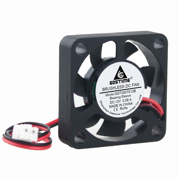
- Delta EFB0412VHD or equivalent fan
- Push-button
- Ceramic Capacitor 1uf x 2
- 1N4148WT diode
- Resistors (10k, 100 ohms, 10k)
- DMG6968U-7 MOSFET
- 10k NTC thermistor
- USBasp programmer
A more comprehensive BOM generated from the schematics is provided in the table below. Since the project is expected to be deployed in a device, the decision was made to use mostly SMD-type components as it will help reduce space occupied by the device.
| Part | Value | Device | Package | Description |
| C1 | 1u | CAP_CERAMIC_0603MP | _0603MP | Ceramic Capacitors |
| C2 | 1u | CAP_CERAMIC_0603MP | _0603MP | Ceramic Capacitors |
| C3 | 1n | CAP_CERAMIC0402_SMALL | 0402_SMALL | |
| D1 | 1N4148WT | DIODESOD-523 | SOD-523 | Diode in 0805 package |
| JP1 | PINHD-1X3 | 1X03 | PIN HEADER | |
| JP4 | 2WAY | 2WAY | ||
| Q1 | DMG6968U-7 | MOSFET-NWAVE | SOT23-W | N-Channel Mosfet |
| R1 | 10k | RESISTOR0402_SMALL | 0402_SMALL | |
| R2 | 100R | RESISTOR0402_SMALL | 0402_SMALL | |
| R3 | 10k | RESISTOR0402_SMALL | 0402_SMALL | |
| SW1 | SPST_TACTG75_3X4 | TACT_SMD5 | ||
| U1 | ATTINY10 | ATTINY10SM_PAD | SOT23-6_SM_PAD | |
| U2 | MCP1703T-5002E/CB | MCP1700T-2502E/TTWIDE_PAD | SOT-23 | Low Quiescent Current LDO |
| X1 | 22-23-2031 | 22-23-2031 | 22-23-2031 | 0.1 |
All of these components can be bought from electronics component suppliers like digikey.
Schematics
As mentioned above, most of the components used are SMD type which means the project is best implemented on a PCB. As such the schematic was designed using Autodesk Eagle CAD. The components are connected as shown in the image below:
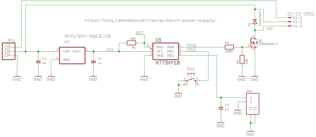
To make it easy to connect the Delta EFB0412VHD fan to the PCB, a 1 x 3 header pin was used.
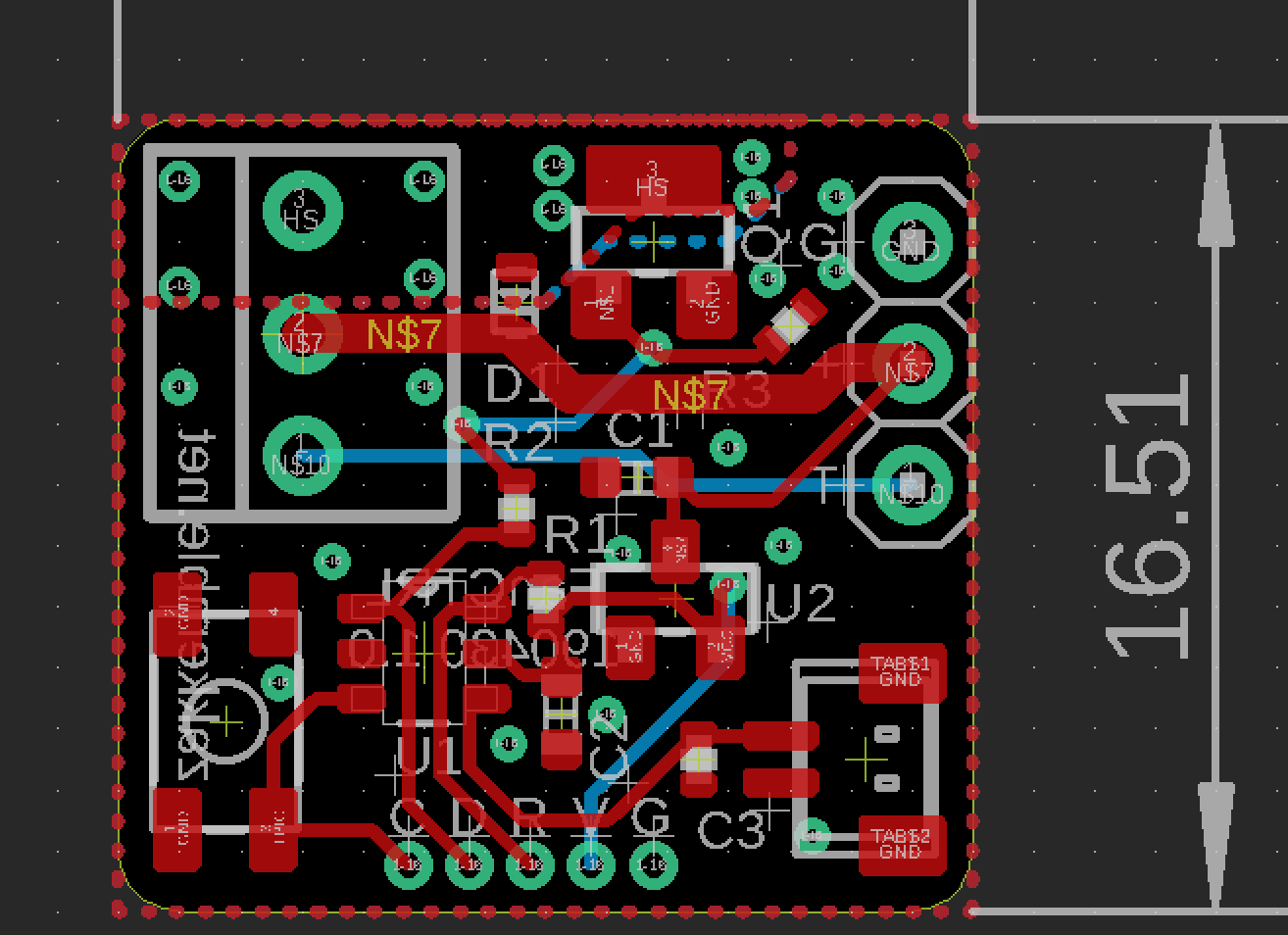
After the schematics design has been done, we then switch to the Eagle Board Layout where the PCB is created. The PCB after routing looks like the image below;
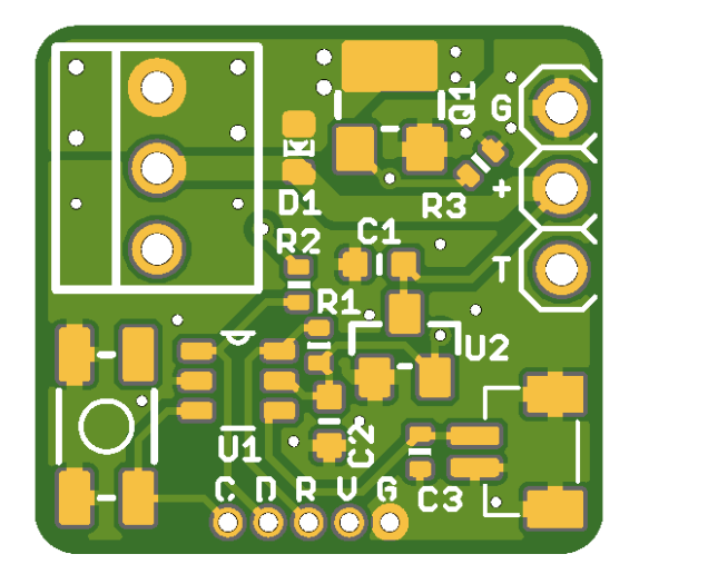
Viewing in 3D to get insight into how things will look after manufacturing:
The schematics and PCB files are provided in a zip file under the download section to make it easy to generate the Gerber files or make any modification you desire on the project.
Preparing the Arduino IDE
While the code for today’s project could have been developed using platforms like Atmel Studio, we will use the Arduino IDE due to it’s popularity and the fact that using it could also teach you a new hack.
Programming the ATtiny10 with the Arduino IDE is a bit different from how the IDE works for other microcontrollers because unlike the SPI protocol used in programming larger AVR chips like the Atmega328p on the Arduino Uno, the ATtiny10 uses a programming protocol called TPI (Tiny Programming Interface) which needs only five wires. As such, it requires modifications in the software and hardware involved.
For software modification, we will need to add the Attiny10 core to the Arduino IDE. While there are a few ATtiny10 cores out there, for this project, we will use the Core developed by Johnson Davies. The core is essentially a boards.txt file that adds options for ATtiny10/9/5/4 to the Arduino IDE’s Board menu so they can be programmed using the Arduino IDE. However, this core doesn’t include the Arduino support core, as a result, it does not support the popular Arduino functions like pinMode(), millis(), etc., so the code must be developed in pure C programming language. To install the ATtiny10 Core, download the core from it’s GitHub page. Extract the zip file, and copy its content to the hardware folder inside the Arduino folder (the same folder where your sketches and Library folder is located) in your Documents folder. If there is no hardware folder, create it before doing any other thing. According to the Github page, the ATtiny10Core should work with all versions of the official Arduino IDE (from arduino.cc) from version 1.6.3 onwards but versions from 1.8.3 and up are recommended.
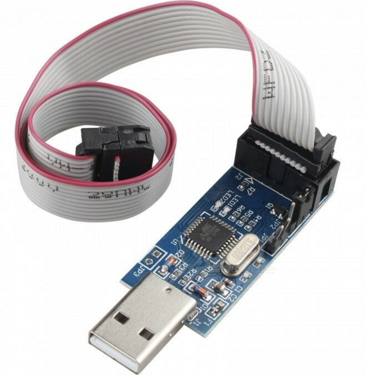
On the hardware side, the popular usb-serial converters cannot be used in programming the ATtiny10 due to the TPI interface requirement but fortunately for us, Thomas Fischl created an excellent USBasp programmer which supports this protocol so you can build your own using his guide or just order one with a 10pin or 6pin adapter for ISP from his website or others like eBay and Banggood.
With all of these in place, we are now ready to write the code for the project.
Code
As mentioned above, the ATtiny10 core being used does not support the Arduino functions so we need to develop the code in pure C/C++. To do this effectively, one needs to understand how the Arduino functions translate in core C/C++ and how ports work. You can check out these explanations to better understand it.
As usual I will do a quick breakdown of the code to explain how each of the parts work.
We start the code by including libraries that allow us use standard AVR register definitions and standard C++ routines.
#include <stdint.h>
#include <avr/io.h>
#include <avr/power.h>
#include <avr/wdt.h>
#include <avr/interrupt.h>
#include <avr/sleep.h>
#include <util/delay.h>
Next, we create variables to hold the state of the fan, intervals at which the temperature is measured, and temperature threshold at which it is declared HOT or COLD.
#define FAN_OVERRIDE_NONE	0
#define FAN_OVERRIDE_ON		1
#define FAN_OVERRIDE_OFF	2

#define FAN_COOL_TIME		125 // 125 * 64ms = 8s // Keep fan on for this much longer after COOL_VAL has been reached
#define TEMP_MEASURE_INTERVAL	32 // 32 * 64ms = 2s // How often to measure temperature

#define HOT_VAL				23 // Sense: 4k @ ??C
#define COOL_VAL			27
Next, we declare that the state of each of the pin should be and the value that should be associated with that state.
#define FAN_ON() (PORTB |= _BV(PORTB0))
#define FAN_OFF() (PORTB &= ~_BV(PORTB0))
#define BTN_ISPRESSED() (!(PINB & _BV(PINB1)))
Next, we create the main function. The main function is similar to the void loop() as it contains the code snippets we hope to run perpetually but unlike the Arduino void loop function, it also contains code snippets similar to what we would have written for the void setup() function. The convention used in the Arduino version can however be retained but for this tutorial we will write the standard C version of the main() function.
We start the main() function by setting the clock and declaring the pin mode of the pin on the port that we will be using as 0 (Indicating the PinMode as input). After this we activate the internal pull up resistors using a separate pullup register, PUEB, power off analog comparators, setup the ADC and power off everything else to save power.
int main(void)
{
  clock_prescale_set(CPU_DIV);

  DDRB |= _BV(DDB0);
  PUEB |= _BV(PUEB1);

  ACSR = _BV(ACD); // Power off analogue comparator

  // Setup ADC
  ADMUX = _BV(MUX1);
  ADCSRA = _BV(ADIE)|_BV(ADPS2)|_BV(ADPS0);
  DIDR0 = _BV(ADC2D);

  power_all_disable(); // Power off everything else
Next we initialize variables that will be used to; hold the last temperature to determine if a change has occurred, check if the button is pressed or not, and start the fan in an override mode. With that done, we set the global interrupt flag by calling sei().
      uint8_t now = 0;
uint8_t lastMeasureTemp = 0;
uint8_t lastHotTime = (0 - FAN_COOL_TIME) + 31; // Turn fan on for 2 seconds at power on
uint8_t hot = 0;
uint8_t btnIsPressed = 0;
uint8_t fanOverride = FAN_OVERRIDE_NONE;

sei();
Next we handle Watchdog resets and finally write the code that compares the temperature level and turns the fan “ON” or “OFF” depending on it while also checking the pushbuttons in every 64ms to see if the mode of use has changed. Depending on the Mode, the Fan can either be activated or not. If the pushbutton is pressed, the system checks the last state of the fan and switches to an opposite state and continues to run in that opposite state until the push button is pressed again. However, if the button is not pressed the fan runs its on and off duty based on the temperature and time.
  sei();

  // Was reset by the watchdog (mainly for debugging)
  if(rstflr_mirror & _BV(WDRF))
  {
    while(1)
    {
      // _delay_ms() is giving some asm error (avr-libc bug? GCC 8.3.0)
      for(uint16_t i=0;i<20000;i++)
      {
        WDT_INT_RESET();
        _delay_us(100);
      }
      //_delay_ms(2000);

      FAN_ON();

      // _delay_ms() is giving some asm error (avr-libc bug? GCC 8.3.0)
      for(uint16_t i=0;i<5000;i++)
      {
        WDT_INT_RESET();
        _delay_us(100);
      }
      //_delay_ms(500);

      FAN_OFF();
    }
  }

  WDT_INT_RESET();

  while(1)
  {
    // Timer stuff, increments every 64ms from the WDT
    // Also turns the WDT back on
    if(WDT_TIMEDOUT())
    {
      WDT_INT_RESET();
      now++;
    }

    if((uint8_t)(now - lastMeasureTemp) >= TEMP_MEASURE_INTERVAL)
    {
      // Pullup enable
      PUEB |= _BV(PUEB2);

      lastMeasureTemp = now;

      // Wait for a bit for voltage to stabilize
      // _delay_ms() is giving some asm error (avr-libc bug? GCC 8.3.0)
      for(uint8_t i=0;i<10;i++)
        _delay_us(100);
      //_delay_ms(1);

      // Do an ADC convertion
      power_adc_enable();
      ADCSRA |= _BV(ADEN)|_BV(ADSC);
      set_sleep_mode(SLEEP_MODE_ADC);
      sleep_mode();
      loop_until_bit_is_clear(ADCSRA, ADSC); // In case we wakeup from another interrupt before the convertion completes
      uint8_t val = ADCL;
      ADCSRA &= ~_BV(ADEN);
      power_adc_disable();

      // Pullup disable
      PUEB &= ~_BV(PUEB2);

      if(val > COOL_VAL)
        hot = 0;
      else if(val < HOT_VAL)
        hot = 1;
      // else we're between the hot and cool values (hysteresis)

      if(hot)
        lastHotTime = now;
    }

    // Don't need to bother with switch debouncing here since we only loop every ~64ms from the WDT
    if(BTN_ISPRESSED() && !btnIsPressed)
    {
      btnIsPressed = 1;

      if(fanOverride == FAN_OVERRIDE_NONE)
      {
        fanOverride = FAN_OVERRIDE_ON;
        FAN_ON();
      }
      else if(fanOverride == FAN_OVERRIDE_ON)
      {
        fanOverride = FAN_OVERRIDE_OFF;
        FAN_OFF();
      }
      else
      {
        fanOverride = FAN_OVERRIDE_NONE;
        if(!hot)
          lastHotTime = now - FAN_COOL_TIME;
      }
    }
    else if(!BTN_ISPRESSED() && btnIsPressed)
      btnIsPressed = 0;

    if(fanOverride == FAN_OVERRIDE_NONE)
    {
      if(hot || (uint8_t)(now - lastHotTime) < FAN_COOL_TIME)
        FAN_ON();
      else
      {
        FAN_OFF();
        lastHotTime = now - FAN_COOL_TIME;
      }
    }

    // Sleep if nothing to do
    cli();
    if(!WDT_TIMEDOUT())
    {
      set_sleep_mode(SLEEP_MODE_PWR_DOWN);
      sleep_enable();
      //sleep_bod_disable();
      sei();
      sleep_cpu();
      sleep_disable();
    }
    sei();
  }
}

EMPTY_INTERRUPT(WDT_vect);
EMPTY_INTERRUPT(ADC_vect);
The complete code for the project is provided below and attached in the zip file under the download section.
#include <stdint.h>
#include <avr/io.h>
#include <avr/power.h>
#include <avr/wdt.h>
#include <avr/interrupt.h>
#include <avr/sleep.h>
#include <util/delay.h>

#define FAN_OVERRIDE_NONE	0
#define FAN_OVERRIDE_ON		1
#define FAN_OVERRIDE_OFF	2

#define FAN_COOL_TIME		125 // 125 * 64ms = 8s // Keep fan on for this much longer after COOL_VAL has been reached
#define TEMP_MEASURE_INTERVAL	32 // 32 * 64ms = 2s // How often to measure temperature

// Temperature sensor resistance is 10k @ 22C
// Sensor resistance goes down as temperature goes up
// Pullup resistance is around 40k
// Lower value = hotter
#define HOT_VAL				23 // Sense: 4k @ ??C
#define COOL_VAL			27

#define WDT_INT_RESET()		(WDTCSR |= _BV(WDIE)|_BV(WDE)) // NOTE: Setting WDIE also enables global interrupts
#define WDT_TIMEDOUT() (!(WDTCSR & _BV(WDIE)))

#define FAN_ON() (PORTB |= _BV(PORTB0))
#define FAN_OFF() (PORTB &= ~_BV(PORTB0))
#define BTN_ISPRESSED() (!(PINB & _BV(PINB1)))

// PB0 = Fan out
// PB1 = Switch in
// PB2 = Temp sense ADC

static uint8_t rstflr_mirror __attribute__((section(".noinit,\"aw\",@nobits;"))); // BUG: https://github.com/qmk/qmk_firmware/issues/3657

void get_rstflr(void) __attribute__((naked, used, section(".init3")));
void get_rstflr()
{
  rstflr_mirror = RSTFLR;
  RSTFLR = 0;

  //wdt_disable();
  wdt_enable(WDTO_60MS);
}

int main(void)
{
  clock_prescale_set(CPU_DIV);

  DDRB |= _BV(DDB0);
  PUEB |= _BV(PUEB1);

  ACSR = _BV(ACD); // Power off analogue comparator

  // Setup ADC
  ADMUX = _BV(MUX1);
  ADCSRA = _BV(ADIE)|_BV(ADPS2)|_BV(ADPS0);
  DIDR0 = _BV(ADC2D);

  power_all_disable(); // Power off everything else

  uint8_t now = 0;
  uint8_t lastMeasureTemp = 0;
  uint8_t lastHotTime = (0 - FAN_COOL_TIME) + 31; // Turn fan on for 2 seconds at power on
  uint8_t hot = 0;
  uint8_t btnIsPressed = 0;
  uint8_t fanOverride = FAN_OVERRIDE_NONE;

  sei();

  // Was reset by the watchdog (mainly for debugging)
  if(rstflr_mirror & _BV(WDRF))
  {
    while(1)
    {
      // _delay_ms() is giving some asm error (avr-libc bug? GCC 8.3.0)
      for(uint16_t i=0;i<20000;i++)
      {
        WDT_INT_RESET();
        _delay_us(100);
      }
      //_delay_ms(2000);

      FAN_ON();

      // _delay_ms() is giving some asm error (avr-libc bug? GCC 8.3.0)
      for(uint16_t i=0;i<5000;i++)
      {
        WDT_INT_RESET();
        _delay_us(100);
      }
      //_delay_ms(500);

      FAN_OFF();
    }
  }

  WDT_INT_RESET();

  while(1)
  {
    // Timer stuff, increments every 64ms from the WDT
    // Also turns the WDT back on
    if(WDT_TIMEDOUT())
    {
      WDT_INT_RESET();
      now++;
    }

    if((uint8_t)(now - lastMeasureTemp) >= TEMP_MEASURE_INTERVAL)
    {
      // Pullup enable
      PUEB |= _BV(PUEB2);

      lastMeasureTemp = now;

      // Wait for a bit for voltage to stabilize
      // _delay_ms() is giving some asm error (avr-libc bug? GCC 8.3.0)
      for(uint8_t i=0;i<10;i++)
        _delay_us(100);
      //_delay_ms(1);

      // Do an ADC convertion
      power_adc_enable();
      ADCSRA |= _BV(ADEN)|_BV(ADSC);
      set_sleep_mode(SLEEP_MODE_ADC);
      sleep_mode();
      loop_until_bit_is_clear(ADCSRA, ADSC); // In case we wakeup from another interrupt before the convertion completes
      uint8_t val = ADCL;
      ADCSRA &= ~_BV(ADEN);
      power_adc_disable();

      // Pullup disable
      PUEB &= ~_BV(PUEB2);

      if(val > COOL_VAL)
        hot = 0;
      else if(val < HOT_VAL)
        hot = 1;
      // else we're between the hot and cool values (hysteresis)

      if(hot)
        lastHotTime = now;
    }

    // Don't need to bother with switch debouncing here since we only loop every ~64ms from the WDT
    if(BTN_ISPRESSED() && !btnIsPressed)
    {
      btnIsPressed = 1;

      if(fanOverride == FAN_OVERRIDE_NONE)
      {
        fanOverride = FAN_OVERRIDE_ON;
        FAN_ON();
      }
      else if(fanOverride == FAN_OVERRIDE_ON)
      {
        fanOverride = FAN_OVERRIDE_OFF;
        FAN_OFF();
      }
      else
      {
        fanOverride = FAN_OVERRIDE_NONE;
        if(!hot)
          lastHotTime = now - FAN_COOL_TIME;
      }
    }
    else if(!BTN_ISPRESSED() && btnIsPressed)
      btnIsPressed = 0;

    if(fanOverride == FAN_OVERRIDE_NONE)
    {
      if(hot || (uint8_t)(now - lastHotTime) < FAN_COOL_TIME)
        FAN_ON();
      else
      {
        FAN_OFF();
        lastHotTime = now - FAN_COOL_TIME;
      }
    }

    // Sleep if nothing to do
    cli();
    if(!WDT_TIMEDOUT())
    {
      set_sleep_mode(SLEEP_MODE_PWR_DOWN);
      sleep_enable();
      //sleep_bod_disable();
      sei();
      sleep_cpu();
      sleep_disable();
    }
    sei();
  }
}

EMPTY_INTERRUPT(WDT_vect);
EMPTY_INTERRUPT(ADC_vect);
Uploading the Code
With the code verified, PCB soldered, and every other thing in place, follow the steps below to upload the code to the Attiny10.
- Connect the USBasp to the ATtiny10 as shown in the diagram above.
- Select the board type from the options under the ATtiny10 core board options under the tool menu. Tools->Board -> ATtiny10
- Under the programmer option, select USBasp as the programmer. Tools -> Programmer-> USBasp
- Hit the upload button
Do note that the code could also be developed using platforms like Atmel Studio and the procedure would have been only a little bit different.
Demo
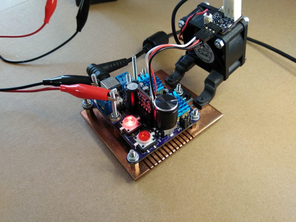
With the code uploaded, connect/mount the smart fan on one of your projects/devices. As the device gets hot or cold, you should see the fan come on and go off.
To test the project, it was connected it to a Bench Power supply and the overall performance was definitely better than when an ordinary heat sink was used. A picture of Zak’s setup is shown in the image below.
That’s it. The idea of the project was to provide you with a module like unit that can be used to maintain acceptable temperature levels in your project. Feel free to reach out to me via the comment section if you have any issue replicating this.
References:


