Using a Soil Moisture Sensor with Arduino
Hi guys, welcome to today's tutorial. Smart farms are becoming very popular as everyone is beginning to see the benefits in terms of crop health and yield and I know a lot of people that will be interested in smart farm automation.
Hi guys, welcome to today’s tutorial. Smart farms are becoming very popular as everyone is beginning to see the benefits in terms of crop health and yield and I know a lot of people that will be interested in smart farm automation. That’s why today, we will be looking at how to use a soil moisture sensor with an Arduino to determine the moisture content in the soil.
Soil moisture is generally the amount of water that is held in spaces between soil particles. It’s is a very important factor that determines the growth of crops and their health.
Instead of the old gravimetric method of measuring soil water content, the soil moisture sensor measures the volumetric water content indirectly by using other properties associated with the soil. The soil moisture sensor used for this tutorial uses electrical resistance of the soil to determine the soil humidity. The electrical resistance of the soil reduces with increase in the amount of water in the soil. The electrical resistance in the soil, however, increases with reduction in the amount of water in the soil. The sensor consists of a probe and a comparator with an adjustable potentiometer which can be used to set the sensitivity of the sensor.
Due to the desire and design techniques of different manufacturers, the sensor comes in different forms, cheap version of the sensor comes with a separate comparator board which is connected to the probe via jumper wires as shown in the image above, this version of the sensor always include an Analog to digital converter which allows the use of the sensor as a digital sensor. Other versions of the sensor from manufacturers like Sparkfun may have all the electronics attached to the probe. Irrespective of the sensor’s form factor, the connections, and use is the same.
Some of the features of this sensor include:
- Operating voltage: 3.3V~5V.
- Adjustable sensitivity (shown in blue digital potentiometer adjustment)
- Dual output mode, analog output more accurate.
- A fixed bolt hole for easy installation.
- With power indicator (red) and digital switching output indicator (green).
- Having LM393 comparator chip, stable.
- Panel PCB Dimension: 3cm x 1.5cm.
- Soil Probe Dimension: 6cm x 2cm.
- Cable Length: 21cm.
The probe of the sensor shown below consists of two large exposed pads that are used to test the electrical conductivity of the soil.
Our goal for this tutorial is to demonstrate how to use this interesting sensor by measuring the soil humidity and displaying the value either on the Arduino Serial monitor or on the Nokia 5110 LCD.
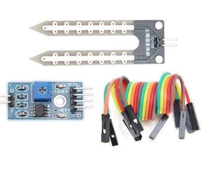
Required Components
The following components are required to build this project;
These components can all be bought via the link attached to each of them.
Schematics
Connect the components as shown in the image below.
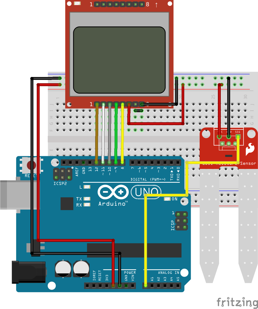
The pin connection between the Arduino and the soil moisture sensor is described below to make the schematics easier to follow.
Moisture Sensor – Arduino
VCC - 5V
GND - GND
SIG - A0
We have covered how to use the Nokia 5110 LCD display in several tutorials on this website so I won’t be going into the details of how to use the display. For those who may find it difficult to follow the schematics, the pin connections for the LCD is also described below.
LCD – ARDUINO
Pin 1(RST) – D12
Pin 2(CE) – D11
Pin 3(DC) – D10
Pin 4(DIN) – D9
Pin 5(CLK) – D8
Pin 6(VCC) - VCC
Pin 7(LIGHT) - GND
Pin 8(GND) - GND
Go over the connection once more to ensure everything is connected as it should be.
Code
Two Arduino sketches are provided for this tutorial. The first one is for those who are comfortable with displaying the data on the serial monitor while the second sketch contains the code necessary to display the soil humidity percentage on the Nokia 5110 LCD display. Since we have covered the use of Nokia 5110 LCD display in several tutorials on this website, I will only explain the first sketch which contains the code to obtain the soil moisture level and display on the serial monitor.
The concept behind the code for this tutorial is simple, since we know the range of the Arduino ADC is between 0 and 1023, we are sure whatever readings the sensor provides will be within that range, thus, when we read the analog value provided by the soil moisture sensor, we use the Arduino map function to convert whatever value was read to a value between 0 and 100, indicating a percentage. The percentage is then displayed on the serial monitor or on the LCD Display. A percentage is used for good UX as it is easier for the user to understand.
To briefly explain the code, the first thing we do is to declare the analog pin of the Arduino to which the moisture sensor is connected after which we declare other variables that will be used later on in our code.
   //////////////////////////////////////////////
  //        ARDUINO SOIL MOISTURE DEMO        //
 //                                          //
//           http://www.educ8s.tv           //
/////////////////////////////////////////////


int sensorPin = A0;
int sensorValue = 0;
int percent = 0;
Next, we move to the void setup() function where we initialize the serial communication so we can display data on serial monitor.
void setup() {
  Serial.begin(9600);
}
Next is the void loop() function. We start the function by reading the value from the sensor then we call the convert to percentage function after which we display the converted value on the serial monitor.
void loop() {

  sensorValue = analogRead(sensorPin);
  percent = convertToPercent(sensorValue);
  printValuesToSerial();
  delay(1000);
}
The code for the conversion to percent function is shown below. As mentioned earlier, it takes in the analog value and converts it to the percentage value using the Arduino map function.
int convertToPercent(int value)
{
  int percentValue = 0;
  percentValue = map(value, 1023, 465, 0, 100);
  return percentValue;
}
The procedure described above is the same for the second sketch, we only need to include dependencies required for the Nokia 5110 LCD Display.
The complete code for the project is attached under the download section of this tutorial.
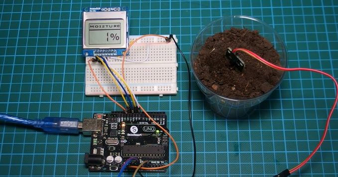
Demo
Upload the code to your Arduino and setup the system with the soil sensor dipped in a fairly dry soil you should see the LCD/serial monitor display the amount of water in the soil as shown in the image below.
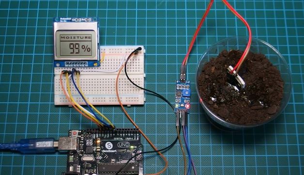
By adding a little amount of water to the soil, the resistance in the soil is lowered and you can see the change immediately on the Display/serial monitor as shown in the image below.
This project is a big step towards smart irrigation system as the change in the soil level can be set to activate a relay to turn on a pump to water plants once the water level is low.
That’s it for this tutorial guys, don’t forget to leave questions, and comments, in the comments section of the tutorial.
Till next time, Keep Building!
The youtube video for this tutorial is available via the attached link