

AquaCont – Aquarium Control
- Pasquale D'Orsi
- pasqualedorsi@gmail.com
- 17.005 Views
- medium
- Non tested
- 0 Likes

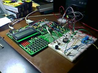
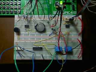
The experimental circuit
The AquaCont is an electronic system witch permits to manage and to monitor most of the parameters of all the electrics devices that can be found in a aquarium. The PIC18F4520 used to realize it, combines a real time clock and a temperature sensor in order to control 8 relays. The system main characteristics are:
-
time / calendar
-
weekly timer for 6 daily events
-
digital temperature sensor
-
additional eeprom memory
-
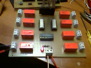
8 outputs controlled by relays joinables to timer events ( 2 of them that can be joined to temperature sensor)
-
LCD display 4×20
-
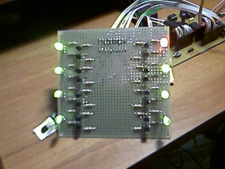
8 bicolour LEDs associated to output ports
-
RS232 serial port for PC communication
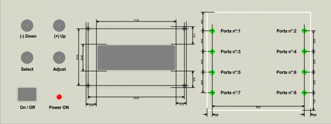
The LCD display permits to monitor the current date and time, the temperature detected by the sensor and moreover it permits to visualize each port status in the last row. In the following LCD screens display it is possible to program the weekly timer events, set the temperature sensor parameters and manage the serial connection with a PC where is running the included WinTimer software.
The power supply needed by the main board is 5V, while the relays board requires 12V; the different source power was useful in granting the protection of the microcontroller and his circuits from overvoltage and short circuit on the 220V. Two optocouplers are utilized for that purpose ensuring the isolation of the different voltages.
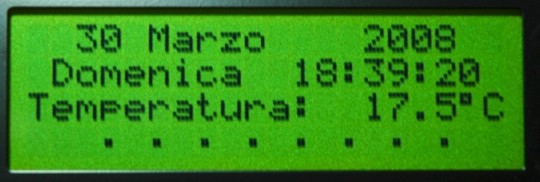
Fig.1 Main screen
The weekly timers are programmed basing on the clock provided by the proper integrated circuit supplied with a lithium battery. The timers data are memorized in the micro’s eeprom. The RS232 serial port allows to simply program the micro using the corresponding PC software; the functions provided in the PC software are also included in the firmware, except for the PC clock syncing. Using the Pc software is also possible to assign a description, to each of the 8 relays ports that will be memorized in the additional LC2416 eeprom memory. In this memory will be also stored the temperature sensor’s settings data.
Block diagram
The following figure shows the block diagram of the system.
Fig.2 Block diagramm
Schematics
Main schematic
Led board schematic
Main board schematic
Relays board schematic
Firmware’s notes
The mikroC language is known for its large functions library and for its good development board so it was used for developing the AquaCont firmware. In fact the first AquaCont prototype was developed using the MikroElektronika’s EasyPIC4 and two breadboards. Please note that the firmware’s source code can be recompiled only using a registered version of MikroC compiler, while the freeware version limits its output to 2K program words.
The AquaCont firmware was conceived from the idea of A. Di Stefano’s macchina a stati, published in his article Realizzazione di un timer digitale programmabile on the 257n of the Fare Elettronica Italian magazine; the original code was obviously modified for making it compatible with the new hardware and new needs. In the new code have
been implemented some new I2C functions for the communication with the Dallas RTC DS1307, the temperature sensor Maxim DS18S20, the eeprom memory 24LC16 and, using the USART functions library, for the RS232 serial port. The original idea of a states structure remained unchanged even if it was implemented with new functionalities and at the same time, updating those already existing. In Fig.4 it is shown the states diagram structure. The stato variable determines which one of the seven function will be executed in the main loop. Every single function is independent and permits to modify the state in relation to the pressed button.
Front Panel
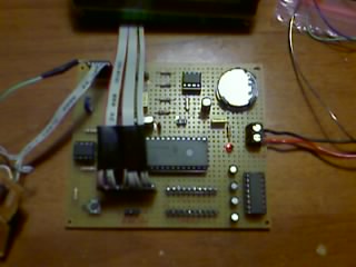
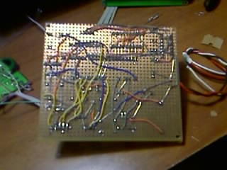
Photos
Download Full project in ZIP (including schematics, boards, firmware ENGLISH and SPANISH, software).


