

PIC based WWVB clock
- Bruce Craig
- bruceandpat@aol.com
- 27.212 Views
- medium
- Tested
- 0 Likes

Introduction
There are many DIY versions of WWVB clock designs available on the web. Commercial “atomic” clocks are inexpensive and widely available, but I wanted to try my hand at designing one to gain insight into WWVB reception and to learn a little about programming a PIC microcontroller. My version is not the simplest available, but it works well and I think it offers a few unique features.
WWVB Clock Features
- Receives time broadcast from WWVB, Fort Collins, CO
- Auto synchronizes internal time with WWVB time
- Maintains local time when WWVB signal is lost
- This version is for Pacific Standard Time, and auto detects/corrects for Daylignt Savings Time
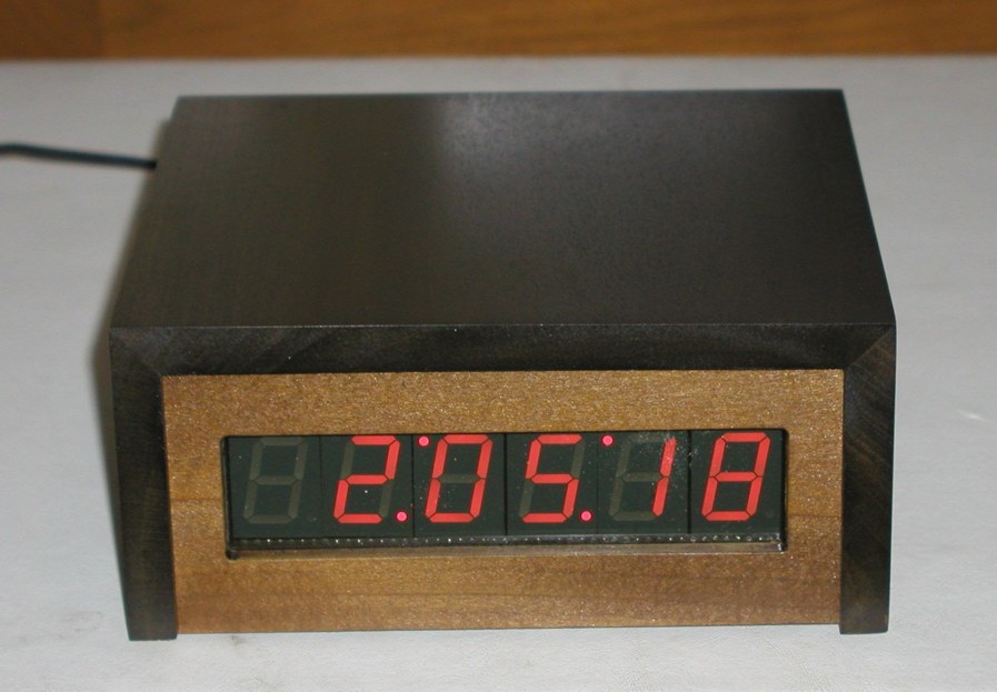
- 6-digit display of hours, minutes, seconds using 1″ seven-segment LED displays
- WWVB sync indicator
- Time display is in 12-hour format
- PIC 16F628 microcontroller
- Software written in C
- All tools (schematic editor, C compiler, PCB layout software, PIC programmer are free and available for download on the web.
A complete description and specification for the WWVB broadcasts is available (free), document # 432, attf.nist.gov/general/pdf/1383.pdf The WWVB signal is broadcast as a 60 kHz carrier that is AM modulated with a time code frame that is updated once per minute. The data rate is one bit per second. Along with time code information, the data frame also contains synchronization bits, calendar data, UT1 correction, leap year, and leap second data. The clock design presented here only decodes the time data and daylight savings correction data. The software could easily be modified to include decoding of the other information bits, if desired. The the low frequency WWVB signal strength is weak and reception can be problematic. Signal acquisition time is variable, depending on location and atmospheric conditions. Reception is usually best at night between 8pm – 4am. To use the clock, just apply power and wait for reception of the WWVB signal. When the clock receives a complete error-free frame of data, it will automatically reset the display to show the correct time. After the initial time correction, the clock will maintain time even if WWVB reception is lost.
Hardware Description
As shown in the schematic (pdf format), the heart of the clock is a PIC 16F628 microcontroller running at 4 MHz. Decoded time data is sequentially output from the microcontroller (RA0 – RA3) to the 7-segment decoder/drivers on a 4-bit data bus. The data is output sequentially as seconds, 10s of seconds, minutes, 10s of minutes, hours, and 10s of hours. The microcontroller outputs (RB1, RB2, RB3) route a 10 uSec stroble pulse from RB4 out to each of the 7-segment decoder/drivers at the proper time to latch the data bus values. Seconds and 10s of seconds display values are updated once per second. Minutes, 10s of minutes, hours, and 10s of hours are updated once per minute. The display consists of 1″ red-orange LED 7-segment displays. The decimal points on the displays are used to form colons to separate the seconds, minutes, and hours. The 10s of seconds and 10s of minutes displays are mounted upside down to form the upper colon dots. The WWVB receiver is a C-MAX model CMMR-6 and is available from Digi-Key (www.digikey.com) as part # 561-1014-ND complete with loopstick antenna. Data output from the receiver is sampled by the microcontroller on RB0.
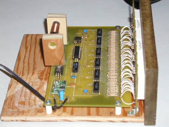
Construction
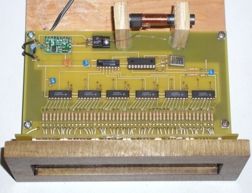
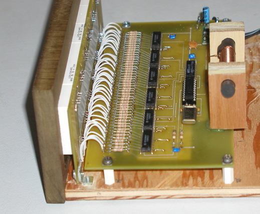
I have built two of these clocks, one using point-to-point wiring and one using a pcb. Both versions perform well. Just keep the receiver away from noise sources and the wire / trace lengths short to minimize inductance. I found that the receiver is also sensitive to magnetic fields produced by power supplies. I used a 9V, 200 mA “wall-wart” instead of an internal power supply to eliminate this problem.
My pcb was designed using Free PCB software www.freepcb.com. The artwork contains both the main board and the display board on a single layout to save the cost of two separate boards. I purchased the pcb from www.4pcb.com by sending them the gerber files and using their “bare-bones” process. The “bare-bones” process does not include solder mask nor silk-screen. Just cut off the display board from the main board and mount it at a right angle to the main board and wire them together using the pads provided.
Software description
I used the Source Boost C compiler to develop the software. It is available for free at www.sourceboost.com
The software is interrupt driven, from the PIC Timer 2 module. The basic timing is set to provide 32 interrupts/sec for both receiver sampling and for internal time propagation. The received data is sampled at 32 samples per second. The software cross correlates the input samples with stored “ideal” samples of the one, zero, and synch patterns. The beginning of a data frame is identified by two consecutive sync bits in a row. When this pattern is detected, the seconds data is reset to zero, and subsequent bits are detected as one’s or zero’s to extract the minutes and hours data. Only the data that is relevant to the time display is decoded. Bits within the data frame that do not contain time data are ignored. The bit detection cross-correlation algorithm requires 31 out of 32 sample agreements between the received data and the stored “ideal” sync pattern.
The decimal point on the seconds digit is turned on when sync is detected and turned off when sync is lost. Bit detection for one’s and zero’s require 28 out of 32 sample agreements between the received data and the stored “ideal” patterns. If any of the detected bits do not meet or exceed the correlation thresholds, the entire frame is discarded and a new search for frame sync is initiated. When sync and all of the time data within a frame is successfully detected, the data is corrected for Pacific Standard Time and Daylight Savings Time. The software must be changed for the proper corrections for other time zones. The time is also corrected for a one minute offset caused by WWVB time being valid at the start of each data frame. The fully corrected time is converted to a 12-hour format and then updates the internal time values. If the WWVB signal is lost, the internal time continues from where it was and relies on the PIC crystal oscillator to propagate time until the next WWVB data frame is received and validated. The PIC16F628 was programmed using WIN PIC software, available for free at
http://www.softpedia.com/get/Programming/Other-Programming-Files/PICProgrammer.shtml
and a “classic” style PIC burner to program the PIC – see
http://www.bobblick.com/techref/projects/picprog/picprog.html
Parts List
In the parts list, I have included the manufacturer and Digi-Key stock number for the ICs and parts that might be difficult to find. The resistors and capacitors are common parts that can be purchased from numerous vendors.
|
Component |
Part Number |
Description |
Manufacturer |
Digi-Key Stock # |
|
IC1 |
PIC 16F628 |
Microcontroller |
Microsemi |
PIC16F628-04/P-ND |
|
IC2 – IC7 |
4511N |
BCD to 7-Segment decoder/driver |
Various |
296-3528-1-ND |
| IC8 | 74HCT138 | 3-8 decoder | Various |
296-1608-5-ND |
| IC9 | 7805 | 5V regulator | Various | LM7805CT-ND |
| R1 – R42 | 150 Ohm 1/8 W | Resistor | Various | |
| R43, R51 | 10 k Ohm 1/8 W | Resistor | Various | |
| R44 – 48 | 270 Ohm 1/8 W | Resistor | Various | |
| Q1 | 4 MHz | Crystal | Various | X971-ND |
| C1, C2 | 20 pf, 50V | Capacitor | Various | |
| C3, C4, C6 | 0.1 uF, 50V | Capacitor | Various | |
| C7 | 10 uF, 35V | Capacitor | Various | |
|
Receiver Module with Antenna |
CMMR-6 | CMAX | 561-1014-ND | |
|
LED1 – LED6 |
LDS-CA14RI |
1″ LED 7-Segment Display |
Lumex |
67-1487-ND |


