

PIC16F688 Digital Voltmeter
- Rajendra Bhatt
- rajbex@yahoo.com
- 44.810 Views
- advanced
- Tested
- 0 Likes

Introduction
This project describes how to make a digital voltmeter using a PIC microcontroller. A HD44780 based character LCD is used to display the measured voltage. The PIC microcontroller used in this project is PIC16F688 that has 12 I/O pins out of which 8 can serve as analog input channels for the in-built 10-bit ADC. The voltage to be measured is fed to one of the 8 analog channels. The reference voltage for AD conversion is chosen to be the supply voltage Vdd (+5 V). A resistor divider network is used at the input end to map the range of input voltage to the ADC input voltage range (0-5 V). The technique is demonstrated for input voltage ranging from 0-20 V, but it can be extended further with proper selection of resistors and doing the math described below.
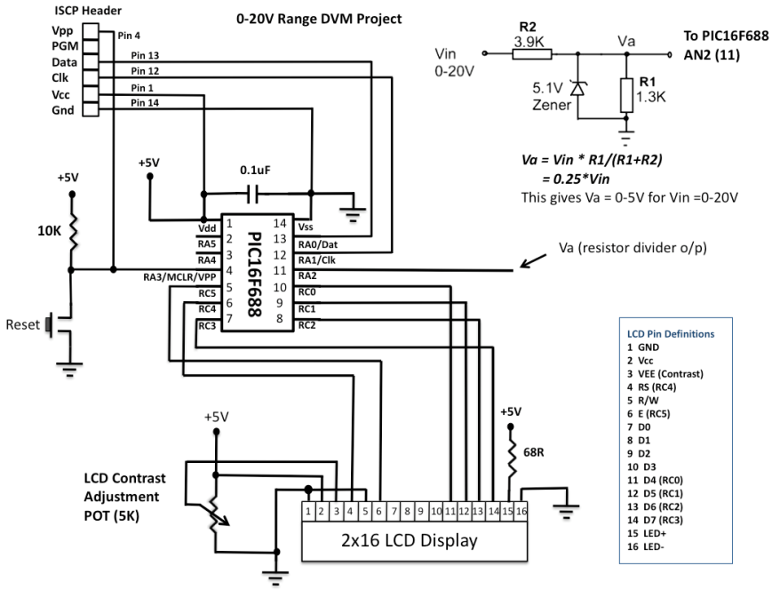
Circuit Diagram
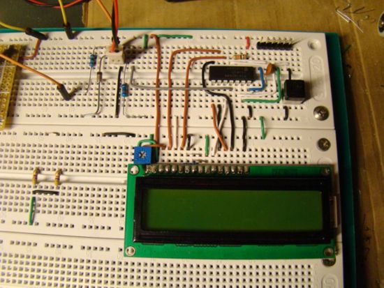
Since the PIC port cannot take 20V input directly, the input voltage is scaled down using a simple resistor divider network. The resistors R1 and R2 scale down the input voltage ranging from 0-20V to 0-5V, before it is applied to PIC16F688s analog input channel, AN2. A 5.1V zener diode connected in parallel between the port pin AN2 and the ground provides protection to the PIC pin in case the input voltage accidentally goes beyond 20V. The LCD display is connected in 4-bit mode, and the ICSP header makes the firmware development easier as you can reprogram and test the PIC while it is in circuit. When you are satisfied and want to transfer the circuit from the breadboard to a PCB or general-purpose prototyping board, you dont need the ICSP header. The circuit diagram and the prototype built on a breadboard are shown below.
Important: You need a regulated +5V supply for accuracy of the output. The ADC uses Vdd as the reference for conversion, and all computations are done with Vdd = 5V. You can get a regulated +5V using a LM7805 linear regulator IC.
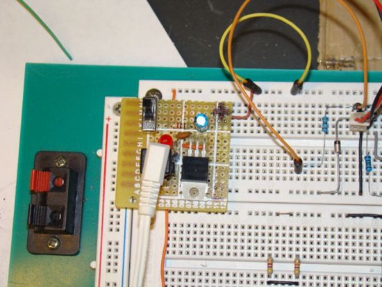
Getting a regulated +5V from a LM7805 IC
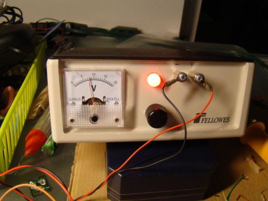
Variable power supply source for testing the DVM
ADC Math
The accuracy depends upon the accuracy of the resistors at the input end and the stability of reference voltage, Vdd = +5V. I found Vdd is stable to +5.02 V. I measured R1 and R2, and their values are 1267 and 3890 Ohms. So this gives:
0 5.02 V Analog I/P —> 0-1023 Digital Count=> Resolution = (5.02 – 0)/(1023-0) = 0.004907 V/CountVa = 1267*Vin/(1267+3890) = 0.2457*Vin=> I/P voltage = 4.07*Va = 4.07* Digital Count * 0.004907 = 0.01997 * Digital Count = 0.02*Digital Count (Approx.)
To avoid floating point, use I/P voltage = 2*Digital Count.
Example, suppose Vin = 7.6V. Then, Va = 0.2457*Vin = 1.87V=> Digital Count = 1.87/0.004907 = 381=> Calculated I/P Voltage = 2*381 = 0762 = 07.6V (First 3 digits of 4 digit product)
Firmware
The firmware is written and compiled with mikroC compiler. The code is here.

/*
  Digital Voltmeter based on PIC16F688
  Rajendra Bhatt, Oct 12, 2010
*/

// LCD module connections
sbit LCD_RS at RC4_bit;
sbit LCD_EN at RC5_bit;
sbit LCD_D4 at RC0_bit;
sbit LCD_D5 at RC1_bit;
sbit LCD_D6 at RC2_bit;
sbit LCD_D7 at RC3_bit;
sbit LCD_RS_Direction at TRISC4_bit;
sbit LCD_EN_Direction at TRISC5_bit;
sbit LCD_D4_Direction at TRISC0_bit;
sbit LCD_D5_Direction at TRISC1_bit;
sbit LCD_D6_Direction at TRISC2_bit;
sbit LCD_D7_Direction at TRISC3_bit;
// End LCD module connections

char Message1[] = "DVM Project";
unsigned int ADC_Value, DisplayVolt;
char *volt = "00.0";

void main() {
  ANSEL = 0b00000100; // RA2/AN2 is analog input
  ADCON0 = 0b00001000; // Analog channel select @ AN2
  ADCON1 = 0x00;
  CMCON0 = 0x07 ; // Disbale comparators
  TRISC = 0b00000000; // PORTC All Outputs
  TRISA = 0b00001100; // PORTA All Outputs, Except RA3 and RA2
  Lcd_Init();        // Initialize LCD
  Lcd_Cmd(_LCD_CLEAR);             // CLEAR display
  Lcd_Cmd(_LCD_CURSOR_OFF);        // Cursor off
  Lcd_Out(1,1,Message1);
  Lcd_Chr(2,10,'V');

do {

   ADC_Value = ADC_Read(2);
   DisplayVolt = ADC_Value * 2;
   volt[0] = DisplayVolt/1000 + 48;
   volt[1] = (DisplayVolt/100)%10 + 48;
   volt[3] = (DisplayVolt/10)%10 + 48;
   Lcd_Out(2,5,volt);
   delay_ms(100);
  } while(1);

 }
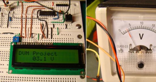
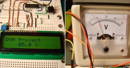
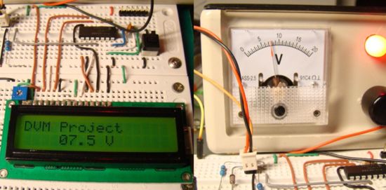
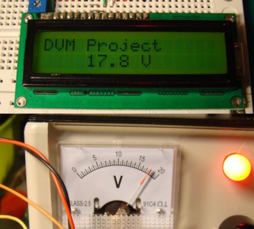
Output
The DVM is tested for various input voltages ranging from 0-20 V and found to be very accurate. Some snapshots of the testing are here.


")
 Converter")

How I measure 30 Volt in this meter… Its show maximum 20.4 Volt….. Can you please give the hex file, without changing the resistors for 30 Volt?. Thank you very much for the wonderfull project. My mail Id = manoj2madhav(at)gmail.com
can u send the project with MPLAB
mail id – gurpreetvssm@gmail.com