

Frequency Division Counters
- Muhammad Shahid
- 12 min
- 164 Views
- 0 Comments
- 4 Likes

Frequency Division
A frequency divider is a circuit that accepts an input signal of a frequency and outputs a signal that is a multiple of a reference frequency. It is also known as a clock divider, scaler, or prescaler.
Only very high frequencies are utilized with analog frequency dividers, which are less frequent. In today’s integrated circuits, digital dividers can operate at tens of GHz.
When a clock signal must be lowered in frequency, a frequency divider is a basic component of digital circuits. Digital communication, frequency synthesis, and data synchronization are among the many uses for frequency dividers.
Frequency Division applications employ toggle flip-flops as binary counters to reduce the frequency of the input clock signal. The output is divide-by-2 of the input.
We know that D-type Flip-Flops are connected to make a Data Latch. The D-type Flip-Flop can also be used as a binary divider, a “divide-by-2” counter, or for frequency division.
Here, as seen below, the device receives “feedback” via the inverted output terminal Q̄ (not-Q), which is directly linked back to the data input terminal D.
Frequency Division Divide-by-2 Counter
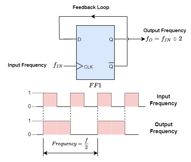
The frequency waveforms above demonstrate how “feeding back” the output from Q to the input terminal D results in output pulses at Q that are precisely half (ƒ ÷ 2) of the input clock frequency. Put another way, the circuit divides the input frequency by two, or one octave, resulting in frequency division.
This results in a particular kind of counter known as a “ripple counter.” A ripple counter is a series of cascading flip-flops where the clock input of the next flip-flop is driven by the output of the previous flip-flop. The modulus of the counter is a parameter that determines how many flip flops are in a cascaded arrangement and how many different logic states the circuit passes through before repeating the sequence. You can count to 2n states using an n-bit ripple counter. It comes by the name MOD n counter as well. The way the clock pulse ripples through the flip-flops is why it’s called a ripple counter.
The Toggle Flip-Flop
The T-type or toggle flip-flop is another kind of digital gadget that may be utilized for frequency division. The single input of a toggle flip-flop is paired with one or two complementary outputs of Q and Q̄, which changes states depending on whether an input clock signal or pulse is on the rising or falling edge. Since they are not commercially available, with a small change to a conventional JK flip-flop, we may design a new sort of flip-flop called a Toggle flip-flop, wherein the J input functions as a Set (S) command and the K input functions as a Reset (R) command.
Toggle flip-flops can be built using D-type flip-flops as seen above, or from ordinary JK flip-flops such as the 74LS73. The end product is a gadget with just two inputs: the actual “Toggle” input and the indicated negative-controlled “Clock” input.
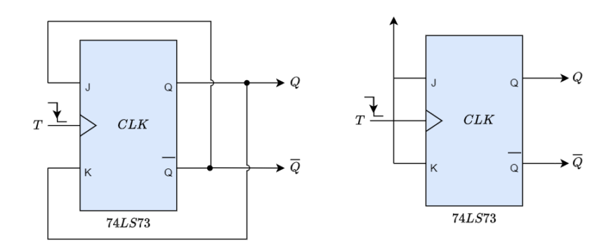
The name “toggle flip-flop” refers to the flip-flop’s capacity to alternate between its two distinct states, the “memory state” and the “toggle state.” A T-type flip-flop is perfect for use in frequency division and binary counter construction as it only has two states.
By joining the output of one “Toggle” or “T-type flip-flop” to the clock input of the subsequent one, binary ripple counters may be constructed. Because toggle flip-flops switch between two states (HIGH to LOW or LOW to HIGH) on each clock cycle, they are perfect for creating ripple counter circuits. Standard T-type flip-flop circuits may be used to create straightforward frequency divider and ripple counter circuits.
When two T-type flip-flops are connected in series, the first flip-flop divides the initial input frequency by two (ƒ ÷ 2), and the second flip-flop divides it again (ƒ÷ 2), yielding an output frequency that has effectively been divided four times. The output frequency then becomes one-quarter value (25%) of the original clock frequency, (ƒ÷ 4).
The output clock frequency is split or halved by two each time a toggle or “T-type” flip-flop is added to the chain, and so on. This results in an output frequency of 2n, where “n” is the total number of flip-flops used in the sequence.
Then, based on the common JK-type flip-flop, the toggle or T-type flip-flop is an edge-triggered divide-by-two device that is activated on the rising edge of the clock signal. Each bit advances right by one flip-flop consequently. It is perfect for frequency division since all the flip-flops can be prompted to switch on either the leading or trailing edge of the input clock signal and can be reset asynchronously.
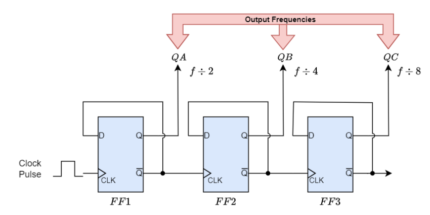
The term “Asynchronous 3-bit Binary Counter” refers to this kind of counter circuit used for frequency division since the output on QA to QC, which is three bits wide, is a binary count ranging from 0 to 7 for each clock pulse.
FF1 in an asynchronous counter is driven by a clock pulse. FF1’s output powers FF2, which in turn powers the flip flop FF3. Every J and K input is linked to Logic 1. As a result, each flip flop’s clock input will toggle with a negative transition. At first, every flip flop is reset to provide a value of 0. The criteria for the output are QC-QB-QA = 000.
On its negative edge, the FF1 changes state upon application of the first clock pulse. Consequently, QC-QB-QA = 001. Flip flop FF1 toggles on the negative edge of the second clock pulse. It produces a range of 1 to 0. FF2 changes state because of this negative alteration. Consequently, QC-QB-QA = 010. Comparably, when the fourth clock pulse is delivered, the flipflop FF3’s output only modifies if there is a negative transition at its input.
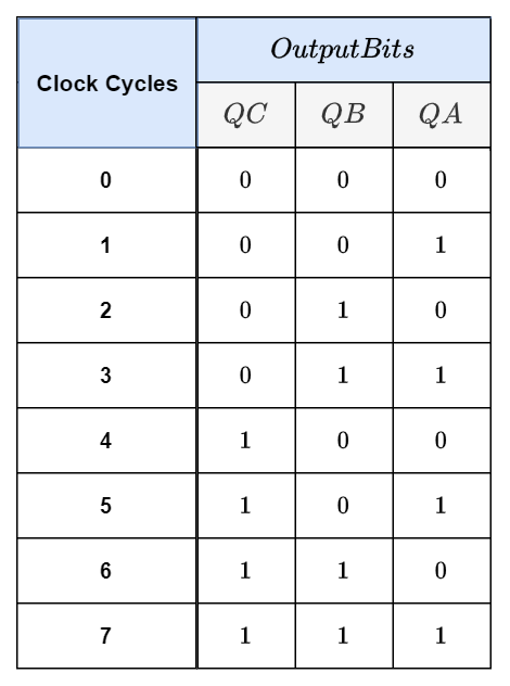
Since no bit in the counter changes at the same time, each clocking event occurs separately, giving rise to the term “asynchronous” arrangement. The counter counts from 0 to 7 consecutively and upwards. A “3-bit Asynchronous Up Counter” or an “up” or “forward” counter (CTU) are other names for this kind of counter. This is a standard three-bit asynchronous counter that operates in toggle mode using flip-flops. There are also asynchronous “Down” counters (CTD) available.
Truth Table for a 3-bit Asynchronous Up Counter
Consequently, the D-type flip-flop counts in twos, or at half the frequency of the input. A divide-by-2, divide-by-4, divide-by-8, etc. circuit that divides the input clock frequency by 2, 4, or 8 times—or by any number to the power of 2—can be created by stacking additional D-type or toggle flip-flops to create a binary counter circuit.
Frequency Division Using Binary Counters
Thus, a counter is nothing more than a specialized register or pattern generator that, when an input pulse signal known as the “Clock” is applied, generates a predetermined output pattern or series of binary values (or states).
In some applications, data transmission is accomplished via the clock. Counters are often logic circuits with the ability to increase or decrease a count by one; however, they may also split these input pulses to produce a clock division signal when utilized as asynchronous divide-by-n counters.
Flip-flops can be joined or “cascaded” together to create a “divide-by-n” binary counter, where “n” is the number of counter stages employed. This is known as the modulus. Flip-flops are the building blocks of counters. A counter experiences the number of output states before going back to zero, or one full cycle, which is known as its modulus, or simply “MOD.”
Then, using the circuit above, a counter with three flip-flops will count from 0 to 7, or 2n-1. Known as a MOD-8 counter, it has eight distinct output states that correspond to the decimal numerals 0 through 7. A counter that has four flip-flops is referred known as a modulo-16 counter since it can count from 0 to 15.
An example of this is given as.
3-bit Binary Counter = 23 = 8 (modulo-8 or MOD-8)
4-bit Binary Counter = 24 = 16 (modulo-16 or MOD-16)
8-bit Binary Counter = 28 = 256 (modulo-256 or MOD-256)
The Modulo number may be increased by adding more flip-flops to the counter and cascading is a means of getting larger modulus counters. The modulo, or MOD number, can therefore be expressed as follows: MOD quantity is 2n.
4-bit Modulo-16 Counter
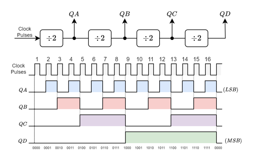
The term “ripple counters” or “ripple dividers” refers to multi-bit asynchronous counters that are linked in this way since the state changes at each step seem to “ripple” through the counter from the LSB output to the MSB output connection. The 74LS393 Dual 4-bit counter and the 74HC4060, a 14-bit ripple counter with an integrated clock oscillator, are the two types of ripple counters that are available in conventional integrated circuit form and provide good frequency division of the fundamental frequency.
Conclusion
- Toggle mode flip-flops are employed in a chain as a divide by two counters for frequency division. The input clock will be divided by two, by using a flip-flop, then by four (by adding another flip-flop) and so on. The output of toggling flip-flops for frequency division has an exact 50% duty cycle at any given time, which is an advantage.
- The input clock frequency divided by the counter’s MOD number will yield the final output clock signal’s frequency value. “Divide-by-n” counters are the name given to these circuits. Individual flip-flops may be joined to create counters, which are categorized based on how they are timed.
- In asynchronous counters, also known as ripple counters, the external clock pulse clocks the first flip-flop, and the output of the flip-flop before it clocks each subsequent flip-flop in turn. All the flip-flops in synchronous counters are linked to the clock input so that they are all timed concurrently.
- We will go through asynchronous counters in the upcoming session. An asynchronous counter’s primary feature is that each flip-flop in the chain gets its clock from the flip-flop before it, making it independent of the input clock.
Please follow and like us:
More tutorials in Counters
Subscribe
Login
0 Comments


