Asynchronous Counter
Asynchronous Counter "Asynchronous counters" are those counters in which where various flip-flops are driven by various clock signals at their clock inputs. Only the first flip-flop in an asynchronous counter is externally synchronized using a clock pulse; all subsequent flip-flops in the counter use the output of the preceding flip-flop as their clock input.
Asynchronous Counter
“Asynchronous counters” are those counters in which where various flip-flops are driven by various clock signals at their clock inputs. Only the first flip-flop in an asynchronous counter is externally synchronized using a clock pulse; all subsequent flip-flops in the counter use the output of the preceding flip-flop as their clock input. Asynchronous counters employ flip-flops wired in series to give the impression of a ripple in the input clock pulse.
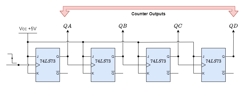
An asynchronous counter is perfect for use in frequency division applications since it may have 2n-1 different counting states, such as MOD-16 is a 4-bit counter, which counts from (0-15). However, the fundamental asynchronous counter setup may also be used to create unique counters with counting states that are less than their maximum output number, and they are termed as MOD counters or modulo.
An asynchronous counter with truncated sequences may be created by forcing the counter to reset itself to zero at a predefined value. Then, an n-bit counter with a modulus less than the maximum value is referred to as a truncated counter, while an n-bit counter that counts to its maximum modulus (2n) is termed a complete sequence counter.
However, why would we wish to construct an asynchronous truncated counter that isn’t a MOD-4, MOD-8, or another modulus raised to the power of two? The answer is that we can by utilizing combinational logic take advantage of the asynchronous inputs on the flip-flop.
It is possible to create a decade (divide-by-10) counter output for use in common decimal counting and arithmetic circuits by modifying the modulo-16 asynchronous counter with extra logic gates.
More precisely, these counters are called “Decade Counters.” When the output count hits the decimal value of 10, or when DCBA = 1010, a decade counter must be reset to zero. To accomplish this, we must send this condition back into the reset input. Although binary decade counters are more frequent, a counter with a count sequence ranging from binary “0000” (BCD = “0”) to “1001” (BCD = “9”) is commonly referred to as a BCD binary-coded-decimal counter since its ten-state sequence is that of a BCD code.
Asynchronous Decade Counter
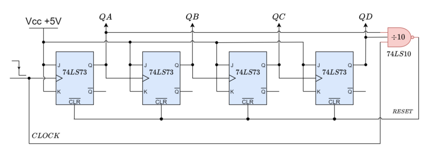
Starting from 0000 and counting higher on each trailing edge of the input clock signal, this kind of asynchronous counter continues until it reaches an output of 1001 (decimal 9). QA and QD’s outputs are now equivalent to logic “1”. When the subsequent clock pulse is applied, the 74LS10 NAND gate’s output switches from a logic “1” level to a logic “0” level.
This signal resets all the Q outputs to binary 0000 on a count of ten since the output of the NAND gate is linked to the CLEAR (CLR bar) inputs of each 74LS73 J-K Flip-flop. The NAND gate’s output goes back to a logic level of “1,” since outputs QA and QD are now both equal to logic “0” due to the flip-flops having just been reset and the counter resumes at 0000. Now, we have a Modulo-10 up-counter or a decade.
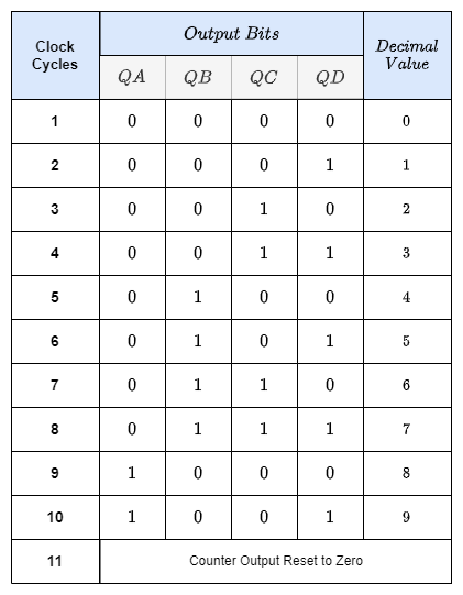
Decade Counter Truth Table
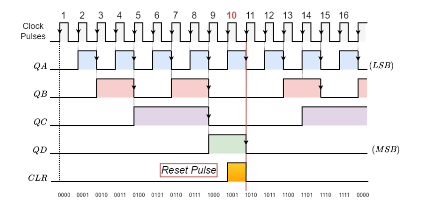
Decade Counter Timing Diagram
The above circuit might be readily modified to accommodate other counting cycles by utilizing the same concept of truncating counter-output sequences and altering the connections to the NAND gate’s inputs or by utilizing different logic gate combinations.
For instance, a scale of twelve (modulo-12) may be created with ease by only feeding the NAND gate’s inputs from the outputs at “QC” and “QD,” keeping in mind that output “QA” is the least significant bit (LSB) and that 1100 is the binary equivalent of 12.
Since 2n is the greatest modulus that can be achieved with n flip-flops, you should choose the lowest power of two that is larger than or equal to your desired modulus when creating truncated asynchronous counters.
Suppose we want to count from 0 to 39, or mod-40. Then, six flip-flops would be the maximum number needed (n = 6), which would result in a maximum MOD of 64. Five flip-flops would not be sufficient since this would only provide a MOD-32, we can verify the same by using the 2n formula.
Assuming we were to construct a “divide-by-128” counter for frequency division, we would require seven flip-flops to cascade since 128 equals 27. Even with twin flip-flops like the 74LS74, four integrated circuits would still be required to furnish the circuit.
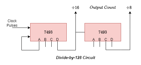
Making a four-bit ripple counter by using two TTL 7493S would be a simple substitute technique. TTL 7493S is a 1:16 counter which can be split into 1:2 and 1:8. One 7493 might be set up as a “divide-by-16” counter and the other as a “divide-by-8” counter because 128 = 16 x 8. As indicated, the two integrated circuits would be cascaded together to provide a “divide-by-128” frequency divider.
Naturally, there are conventional integrated circuit asynchronous counters out there. For example, the TTL 74LS90 programmable ripple counter/divider may be set up to divide by two, divide by five, or in any combination of the two. There are several “divide-by” choices available for the 74LS390, an extremely versatile dual-decade driver integrated circuit. These combinations include divide-by-2, 4, 5, 10, 20, 25, 50, and 100.
Frequency Dividers
Because ripple counters may truncate sequences to create a “divide-by-n” output, they are particularly useful as frequency dividers, bringing a high clock frequency down to a more manageable number for use in timing and digital clock applications. Let’s take an example where we need to run a digital clock on an exact 1Hz timing signal.
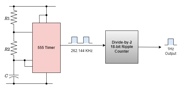
With a standard 555 timer chip set up as an Astable-Multivibrator, we could easily generate a 1Hz square wave signal. However, the manufacturer’s data sheet informs us that the 555 timer typically has a 1-2% timing error, depending on the manufacturer, and that this 2% timing error is not good at low frequencies like 1Hz.
The data sheet also states that the 555 timer’s highest working frequency is around 300 kHz, and at this high frequency—which is still rather significant at a maximum of 6 kHz—a 2% inaccuracy would be acceptable. Therefore, we may simply create a precise 1Hz timing signal as shown below by using a higher timing frequency, such as 262.144kHz, and an 18-bit ripple (Modulo-18) counter.
1Hz timing signal from an 18-bit asynchronous ripple counter
Naturally, this is a very basic example of how to create precise timing frequencies. However, precision frequency generators can be created for a wide range of uses, including watches, clocks, event timing, electronic pianos and synthesizers, and music-related applications, by utilizing high-frequency crystal oscillators and multi-bit frequency dividers.
Unfortunately, one of the primary drawbacks of asynchronous counters is that, because of the internal circuitry of the gate, there is a slight delay between the arrival of the clock pulse at its input and its presence at its output.
The term “propagation counter” refers to this delay in asynchronous circuits, and in certain high-frequency scenarios, it might result in erroneous output for the asynchronous ripple counter.
A significant time gap may occur between the input signal and the counted output signal in big bit ripple counter circuits if the delays of the individual stages are combined up to produce a summed delay at the end of the counter chain. Hence, in high-frequency counting circuits involving many bits, the asynchronous counter is typically not utilized.
Additionally, because of its clocking sequence, the counter’s outputs do not occur at the same instant in time or have a set temporal connection with one another. Stated differently, there is a cascading effect of output frequencies becoming accessible one after the other. To ensure accurate counting, the maximum operating frequency of an asynchronous counter chain decreases with the number of flip-flops added to it. A solution to the propagation delay issue was the development of synchronous counters.
A Ring counter is another application of an asynchronous counter, in which the input of the subsequent flip flop in a ring is coupled to the output of the previous one. When using n flip-flops, a single-bit pattern is typically cycled to repeat the state of every n-clock cycle. It started with only one flip-flop in the state one and the rest in the zero state.
A Johnson counter is a type of modified ring counter in which the final stage’s output is fed back into the initial flip-flop after being inverted. For an endless period, the register cycles through a set of bit patterns whose length is double that of the shift register. It is frequently encountered in converters that convert digital to analog.
Advantages of Asynchronous Counters:
- It is simple to create Asynchronous Counters using D-type or toggle flip-flops.
- The primary feature of a synchronous counter is that all the flip-flops in the chain have a clock input attached to it, allowing all the flip-flops to be timed concurrently.
- Every output in the chain is dependent on how the state of the preceding flip-flop output has changed.
- The reason asynchronous counters are frequently referred to as ripple counters is that the data seems to “ripple” from one flip-flop’s output to the next input.
- To implement them, “divide-by-n” counter-circuits can be used.
- Any modulus number count may be generated using truncated counters.
- These are utilized in situations where minimal power consumption is necessary.
Disadvantages of Asynchronous Counters:
- It might be necessary to add another “re-synchronizing” output flip-flop.
- Additional feedback logic is needed to count a shortened sequence that is not equal to 2n.
- When many bits are being counted, the propagation delay caused by the subsequent phases may increase unnecessarily.
- They are referred to as “Propagation Counters” because of this delay.
- When clocking frequencies are high, counting mistakes happen.
- Since synchronous counters employ a single clock signal to drive every flip-flop, they are more dependable and quicker.
Conclusion
- The main application of an asynchronous counter is to produce a shorter sequence that can be created by forcing the counter to reset itself to zero at a predefined value. Therefore, an n-bit counter whose modulus is less than the maximum value is referred to as a “truncated counter”.
- “Decade Counters.” A decade counter resets to zero when the output count reaches the decimal value of 10, or when DCBA = 1010. Binary decade counters are increasingly prevalent; a BCD binary-coded-decimal counter is a counter having a count sequence that goes from binary “0000” (BCD = “0”) to “1001” (BCD = “9”).
- It would take seven flip-flops to construct a “divide-by-128” counter for frequency division, i.e. 128 = 27. An easy workaround would be to use two TTL 7493s to create a four-bit ripple counter. One 7493 might be configured as a “divide-by-16” counter and the other as a “divide-by-8” counter, resulting in 128 = 16 x 8.
- By employing multi-bit frequency dividers made of asynchronous counters and high-frequency crystal oscillators, frequency generators may be made for a variety of applications, such as watches, clocks, and event timing.
- A propagation counter is a large time interval that may appear in several bits ripple counter circuits, its the delay between input signal and the counted output signal, when the delays of the different stages add up to cumulative delay at the end of the counter chain. Because of this, the asynchronous counter is rarely used in high-frequency counting circuits with several bits.
- Asynchronous counters are also utilized in Johnson counters, Ring counters, and frequency divider circuits.


