Help on how to test this device

Status
Not open for further replies.

mikey5791

Jun 7, 2013
174
Joined
Jun 7, 2013
Messages
174
Hi all,

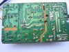
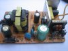
Recently I acquired this mini DC supply adapter,but it lack of any cover with missing mains AC cord 220V. The only identification on the pcb is YY 121 but I am not sure what is the output DC voltage.

Before I connect a new mains AC cord (the two yellow wire),what are the test I need to do on the component level? I have a digital multi meter,an analogue multi meter,digital capacitor tester and a soldering iron. I have basic soldering skills and had successfully repaired a few faulty LCD monitor. For this unknown device, I have checked the continuity of the black square fuse to be ok and all black colour diode is normal (high resistance one side and no resistance the other side).
Attached five thumbnail pictures for reference.

Any help and kind advice is appreciated.
 

Attachments

  • IMG_0927-top.JPG
    IMG_0927-top.JPG
    206.6 KB · Views: 105
  • IMG_0928-AC.JPG
    IMG_0928-AC.JPG
    177.9 KB · Views: 98
  • IMG_0929-DC.JPG
    IMG_0929-DC.JPG
    185.5 KB · Views: 96
  • IMG_0931-back.JPG
    IMG_0931-back.JPG
    284.5 KB · Views: 103
  • IMG_0935-side.JPG
    IMG_0935-side.JPG
    193.1 KB · Views: 125

Martaine2005

May 12, 2015
5,276
Joined
May 12, 2015
Messages
5,276
Hi Mike,
It looks like the transformer has snapped! Or is it just the tape around it?
Secondly, desolder the black DC wires, they look like they are shorting each other.
Thirdly, the two caps by the DC output should give a clue to the output voltage.
They will be higher voltage rated than the output.
The tracers have been beefed up, so it is probably quite a high current output too.

Wait and see what others say regarding the transformer before trying to power it up..

Martin
 

Minder

Apr 24, 2015
3,561
Joined
Apr 24, 2015
Messages
3,561
That just appears to be a outer cover strip, the lamination's look intact to me.
M.
 

Alec_t

Jul 7, 2015
3,817
Joined
Jul 7, 2015
Messages
3,817
The transformer core looks to have split. One leg isn't vertical. There's a distinct shadow by the gap in the tape in IMG-0927.
 

davenn

Moderator
Sep 5, 2009
14,470
Joined
Sep 5, 2009
Messages
14,470
The transformer core looks to have split. One leg isn't vertical. There's a distinct shadow by the gap in the tape in IMG-0927.

yup agree totally ... the core has snapped

you are not likely to get a replacement .... the PSU is file 13 ( rubbish bin) bound

That just appears to be a outer cover strip, the lamination's look intact to me.

there are no laminations ... its a ferrite core !!

Dave
 

dorke

Jun 20, 2015
2,342
Joined
Jun 20, 2015
Messages
2,342
Alec_t is correct-see enlarged photo
I wouldn't bother with that "junk".
BTW,It looks such bad quality anyways-get a new one.
 

Attachments

  • Noname.jpg
    Noname.jpg
    55.8 KB · Views: 78

mikey5791

Jun 7, 2013
174
Joined
Jun 7, 2013
Messages
174
Hi Martaine,Davenn,Alec_t and others

Thanks for reply.
Yes the transformer core(black soft magnetic core) has snapped and split on top. Is there any safe way to repair the split core ? Can I use super glue to join? Or is it safer to throw away?

Martaine,

FYI, the big green cap near AC is rated 400V 10uF while the middle black cap is 50V 33uF. The two green caps near DC supply is rated 16V 330uF.
So am I correct to guess the output DC is about 12V ?
You mentioned that the tracers have been beefed up too with a high current output, but how do you know from your past experience? I am eager to learn.
I will desolder the black DC wires and check all questionable component before any attempt to power it up.

Appreciate all suggestions and advice.
 

dorke

Jun 20, 2015
2,342
Joined
Jun 20, 2015
Messages
2,342
What you have is a direct mains SMPS.
They have dangerous AC/ DC high voltages in them.that can kill you !
What is written on IC1,U1,OP1 ?

Yours is a junk,a very bad quality item(even new)!
Buy a new one of better quality,they are cheap.

You can start learning about them here:
http://www.zl2pd.com/introSMPS.html
 

HellasTechn

Apr 14, 2013
1,579
Joined
Apr 14, 2013
Messages
1,579
The fact that the ferrite has snaped does not necessarily mean that the transformer does not work.

It may be safer to throw away but still it can be used under certain circumctances given that the transformer is ok and the circuit is not burned.

The switching mood power supplies are always enclosed in plastic boxes so that the 110 or 220 Vac will not harm anyone.

In your case it all depends on what you want to do with this psu.
 

HellasTechn

Apr 14, 2013
1,579
Joined
Apr 14, 2013
Messages
1,579
You should also check the fuse. if it is blown then most likely the mosfet is burned. You should check the mosfet also and the diodes that form the bridge rectifier and the 400Volt smoothing capacitor with your meter.
 

davenn

Moderator
Sep 5, 2009
14,470
Joined
Sep 5, 2009
Messages
14,470
The fact that the ferrite has snaped does not necessarily mean that the transformer does not work.

It may be safer to throw away but still it can be used under certain circumctances given that the transformer is ok and the circuit is not burned.

but the transformer IS NOT Ok. its physically damaged and as a result trying to use it is really not a good idea
because the magnetic field through the ferrite core will now be discontinuous, the transformer ratings will be severely derated

Dave
 

HellasTechn

Apr 14, 2013
1,579
Joined
Apr 14, 2013
Messages
1,579
but the transformer IS NOT Ok. its physically damaged and as a result trying to use it is really not a good idea
because the magnetic field through the ferrite core will now be discontinuous, the transformer ratings will be severely derated

Dave
Agreed but given that the other components are ok then testing it under mains voltage will probably not do any harm.

Considering replacement of the board is indeed recommended.
 

mikey5791

Jun 7, 2013
174
Joined
Jun 7, 2013
Messages
174
Hi Dorke,

The info as you requested are as follows:
U1 (3 leg transistor) 431L
F20
JRC
IC1 (3 leg transistor) H949
TO......(unclear)
10.......(unclear)
OP1 (4 leg opto) 40027
17A
F1 (fuse) NSF T2.5A 250V

Hi HellasTechn,

Tested the F1 fuse by checking continuity diode test X1, the analogue meter moves showing continuity.
Is the IC1 the mosfet as you mentioned ? How do I test the mosfet?
If the mini SMPS is repairable, I wish to use it to power some small project such as electronic kit where current requirement is not that high.

Appreciate your kind feedback. Thank you all.
 

dorke

Jun 20, 2015
2,342
Joined
Jun 20, 2015
Messages
2,342
I don't think it is worth repair!
U1 is a voltage reference/regulator (TL431 like)
OP1 is an opto-transistor
IC1 is a power transistor, I think it is probably Bipolar and not Mos.
The circuit looks similar to the flowing design
 

Attachments

  • simple_smps.png
    simple_smps.png
    5 KB · Views: 68

HellasTechn

Apr 14, 2013
1,579
Joined
Apr 14, 2013
Messages
1,579
I
IC1 is a power transistor, I think it is probably Bipolar and not Mos.

I am not sure. i think it is a mos because mosfets are commonly used when it comes to switcing.

Mikey could you tell us what is written on ic1 ?
 

HellasTechn

Apr 14, 2013
1,579
Joined
Apr 14, 2013
Messages
1,579
Hi HellasTechn,

Tested the F1 fuse by checking continuity diode test X1, the analogue meter moves showing continuity.
Is the IC1 the mosfet as you mentioned ? How do I test the mosfet?
If the mini SMPS is repairable, I wish to use it to power some small project such as electronic kit where current requirement is not that high.

Appreciate your kind feedback. Thank you all.

If it really is a mosfet here is a quick way to test it !


dorke

Jun 20, 2015
2,342
Joined
Jun 20, 2015
Messages
2,342
Hi HellasTechn,
This design seems to lack any "PWM control".
That is why I think it is a bipolar transistor and not a MOSFET...
 

duke37

Jan 9, 2011
5,364
Joined
Jan 9, 2011
Messages
5,364
The magnetic circuit may need a gap. This likely since the cores have moved. Do you know what the gap should be and how to set it?

I strongly suggest that you do not use this device since it depends on isolation from mains to output. If this has been compromised either by a faulty component or a deposit of evaporated metal, you may not be available to post again.
 
Status
Not open for further replies.
Top