My Avatar

Xeno Xenox

Mar 13, 2016
50
Joined
Mar 13, 2016
Messages
50
I needed an avatar for Electronics Point and wanted something with a personal touch that was also relevant to the audience.

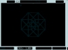
I've always been fond of hypercubes, so I thought it would be fun to generate one on my scope and capture the bitmap for my avatar.

Earlier today, I wrote a program to solve a hypercube as a maze by walking from node to node, traversing each edge only once and returning to the starting point at the end of the sequence, so I can loop it as a repeating cycle.

The program outputs data for two waveforms, representing the X and Y components of the hypercube. These are then fed into a two channel programmable function generator:

upload_2016-6-8_22-51-27.png

When the scope is put into X-Y mode, the hypercube appears:

upload_2016-6-8_22-52-34.png

The function generator gets the job done, but it isn't elegant. The next step is to generate the waveform with an ATtiny and build it out as a small and simple self-contained circuit.
 

hevans1944

Hop - AC8NS
Jun 21, 2012
4,968
Joined
Jun 21, 2012
Messages
4,968
I thought a hyper-cube rendered in 2D looked like a cube nested inside a larger cube with lines connecting the eight corners of each cube. Most of the time I have seen this done with wire frames and soap bubbles. Still, digitally generated Lissajous figures are fun to play with. Good job, and good "out of the box" thinking. We like that here!
 

Xeno Xenox

Mar 13, 2016
50
Joined
Mar 13, 2016
Messages
50
I thought a hyper-cube rendered in 2D looked like a cube nested inside a larger cube with lines connecting the eight corners of each cube. Most of the time I have seen this done with wire frames and soap bubbles. Still, digitally generated Lissajous figures are fun to play with. Good job, and good "out of the box" thinking. We like that here!

That is another way to render a hypercube in 2D. The difference is that mine is an orthographic projection and the one you described is a perspective projection.

The same applies to drawing a cube in 2D. You can draw two identical squares whose corners are connected with diagonal lines (orthographic) or you can draw a small square inside a larger one and connect their corners with lines (perspective).

If a hypercube or cube is close to the viewer (relative to its size), perspective is important. If the hypercube or cube is far away (like a six-sided die sitting a few feet away on a table), then the 2D projection approaches the orthographic case.
 

hevans1944

Hop - AC8NS
Jun 21, 2012
4,968
Joined
Jun 21, 2012
Messages
4,968
@Xeno Xenox, I am gonna take a wild-ass guess and say you are probably really good with topology, too. Thanks for the explanation. It has never occurred to me that everything can be looked at from all sorts of different perspectives and projections, although during every-day life, I think I at least subconsciously try to keep an open mind and make efforts to "think outside the box"... assuming I can figure out who, what, when, and where the damn box is, and why it should concern me.
 

Xeno Xenox

Mar 13, 2016
50
Joined
Mar 13, 2016
Messages
50
For the circuit version, I used an ATtiny25 with RC low-pass filters connected to two PWM outputs:

upload_2016-7-3_12-48-57.png

The resulting scope trace is noisier, but it's quite recognizable:

upload_2016-7-3_12-51-33.png

To answer the question from @bigone5500, I based my design on information gathered from the ATtiny25 datasheet, the book "Make: AVR Programming" by Elliot Williams and the following application note from Atmel on configuring the ATtiny25 for high speed (64 MHz internal clock rate) PWM:

http://www.atmel.com/images/atmel-2542-using-the-avr-high-speed-pwm_applicationnote_avr131.pdf

I am driving the PWM clock at 32 MHz in the above scope trace, because it results in fewer stray readings and the best image overall.
 

Attachments

  • upload_2016-7-3_12-50-50.png
    upload_2016-7-3_12-50-50.png
    7.9 KB · Views: 128

bigone5500

Apr 9, 2014
712
Joined
Apr 9, 2014
Messages
712
For the circuit version, I used an ATtiny25 with RC low-pass filters connected to two PWM outputs:

View attachment 27691

The resulting scope trace is noisier, but it's quite recognizable:

View attachment 27693

To answer the question from @bigone5500, I based my design on information gathered from the ATtiny25 datasheet, the book "Make: AVR Programming" by Elliot Williams and the following application note from Atmel on configuring the ATtiny25 for high speed (64 MHz internal clock rate) PWM:

http://www.atmel.com/images/atmel-2542-using-the-avr-high-speed-pwm_applicationnote_avr131.pdf

I am driving the PWM clock at 32 MHz in the above scope trace, because it results in fewer stray readings and the best image overall.
I'm going to assume I can use an ATTiny85 to do the same thing...??? What are the cap and resistor values you used? Also, what scope did you use to capture the image? Built in function generator?
 

Xeno Xenox

Mar 13, 2016
50
Joined
Mar 13, 2016
Messages
50
I'm going to assume I can use an ATTiny85 to do the same thing...??? What are the cap and resistor values you used? Also, what scope did you use to capture the image? Built in function generator?

Absolutely!

I believe the only difference is the ATtiny85 has four times as much memory as the ATtiny25.
 

Xeno Xenox

Mar 13, 2016
50
Joined
Mar 13, 2016
Messages
50
What are the cap and resistor values you used? Also, what scope did you use to capture the image? Built in function generator?

I used R = 1K and C = 0.1uF, which gives a cut-off frequency around 1600 Hz.

I used a Rigol DS1102E oscilloscope in X-Y mode to view the waveforms. The hypercube images you see are bitmap screen captures directly from the scope to a USB thumb drive.

The wires you see in the circuit photo above are just +5 Vcc (one red wire) and GND (two dark blue wires). There are no other inputs to the circuit. To program the ATtiny25, I used an Arduino and WinAVR. There are great instructions for this in the first chapter or two of the "Make: AVR Programming" book by Elliot Willams.
 
Top