Transistor gate voltage

sommech7498

Aug 13, 2017
4
Joined
Aug 13, 2017
Messages
4
Hey guys. I'm new to electronics here and need help figuring out a circuit I'm trying to make.
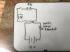
I've attached an image below of the circuit I'm trying to make. Basically this is a tester for automotive purposes.it's a 12v circuit with a 100w rheostat/pot I'm using as a load. I will only be turning it on for a second or 2 max and really only plan on running 4-5 amps through it but want to be capable lf more if needed. I want to be able to turn on the transistor with a 9v and have the transistor and battery mounted on a pcb. I have 2 questions for this circuit. 1 is what kind of transistor should I be using. And 2 is how can I figure out what resistor to use for the transistor gate? Thanks for the help in advance.
 

Attachments

  • IMG_0095.JPG
    IMG_0095.JPG
    162.1 KB · Views: 108

bigone5500

Apr 9, 2014
712
Joined
Apr 9, 2014
Messages
712
Last edited:

Alec_t

Jul 7, 2015
3,818
Joined
Jul 7, 2015
Messages
3,818
With a FET, as above, you wouldn't need a resistor in series with the gate, but you would need one (say 33k or so, not critical) between the gate and the source pins to ensure the FET turns off when the switch opens.
 

AnalogKid

Jun 10, 2015
3,050
Joined
Jun 10, 2015
Messages
3,050
Your drawing has two wires going to what I think you mean to be the base of a bipolar transistor (not a FET). Also, there is no connection between the base circuit and the emitter, so it looks like nothing will happen.

In your post, you don't say what it is you want the circuit to do. If you want the transistor to act as an on-off switch to put an adjustable load on the 12 V battery, you're not there yet. There are two circuit loops, one putting current into the base and one putting current into the collector. Both of these currents go through the emitter, which is why it has to somehow be common to both current loops.

Rather than us give you a solution, why don't you do a little more research and take another swing?

ak

ak
 

twister

Feb 12, 2012
172
Joined
Feb 12, 2012
Messages
172
When ever you have two voltage sources it is a good idea to separate them with a optical switch.
 

AnalogKid

Jun 10, 2015
3,050
Joined
Jun 10, 2015
Messages
3,050
Not in this case. Having a separate voltage source for the transistor base ensures that the base current does not fluctuate if the 12 V source being tested sags under load.

Also - IF you want the transistor to act as a switch rather than as a constant current source - the rheostat should be moved to the collector side of the transistor. This eliminates the possibility of the transistor not saturating because the resistance is too high, and burning up.

ak
 

sommech7498

Aug 13, 2017
4
Joined
Aug 13, 2017
Messages
4
Yea I didn't think about that for the rheostat. Thanks. would a mosfet be better for this situation? If I used a mosfet do I need to even have a resistor before the gate? Could I just give it the full 9 volts from the battery and hook the - of the battery up to the drain?
 

Audioguru

Sep 24, 2016
3,656
Joined
Sep 24, 2016
Messages
3,656
A 100W rheostat was used 100 years ago. Where will you find one today? Today we use a pulse-Width-modulation circuit controlled by a small inexpensive potentiometer or computer.
 

dorke

Jun 20, 2015
2,342
Joined
Jun 20, 2015
Messages
2,342
Can you explain what is the purpose of this circuit,is it to be a battery load?
 

AnalogKid

Jun 10, 2015
3,050
Joined
Jun 10, 2015
Messages
3,050
If I used a mosfet do I need to even have a resistor before the gate?
No.
Could I just give it the full 9 volts from the battery
Yes.
and hook the - of the battery up to the drain?
No. Both battery negative terminals and the n-channel MOSFET *source* are tied together as the system ground. The drain goes to the rheostat, which goes to the +12. Add a 10K resistor from the FET gate to source so it turns off crisply when the +9 V is removed.

ak
 

Bluejets

Oct 5, 2014
7,374
Joined
Oct 5, 2014
Messages
7,374
Why not just remove the transistor all together?
Seems not to be operated by anything external.
If an interface between two voltages, then a simple relay.
 

sommech7498

Aug 13, 2017
4
Joined
Aug 13, 2017
Messages
4
Can you explain what is the purpose of this circuit,is it to be a battery load?
Yes basically it's gonna load a circuit and let me check the battery and or wiring
Why not just remove the transistor all together?
Seems not to be operated by anything external.
If an interface between two voltages, then a simple relay.
right now I have a regular switch doing this and I was gonna use a relay but I want to make this as small as possible. Later on down the road I'd like to add some other things to the circuit and a transistor would be ideal for me
 

AnalogKid

Jun 10, 2015
3,050
Joined
Jun 10, 2015
Messages
3,050
Why not just remove the transistor all together?
Seems not to be operated by anything external.
If an interface between two voltages, then a simple relay.
The idea is to control a very large current with a much smaller current through a much smaller switch. A 100 A - 200 A contactor is far more expensive and less reliable than a suitably rated power transistor.
 
Top