5 volt Arduino? I tweaked the code as much as possible, they all work fine with the software. all I need to do is make the peaks more readable and maintain the signal strength.Interesting. The circuit works fine with an Arduino. The problem can be that it is too sensitive.
You are using an out of date browser. It may not display this or other websites correctly.
You should upgrade or use an alternative browser.
You should upgrade or use an alternative browser.
Scroll to continue with content
- Joined
- Jan 21, 2010
- Messages
- 25,510
all I need to do is make the peaks more readable and maintain the signal strength.
What do you mean? Especially about "maintain".
Ideally (presumably) you would want the voltage to fall back down to 0 asap after reading the peak voltage.
your very old NE5532 opamps do nothing because they are not powered on your schematics. They probably need a positive and negative dual polarity supply.
Yes but without any lossesWhat do you mean? Especially about "maintain".
Ideally (presumably) you would want the voltage to fall back down to 0 asap after reading the peak voltage.
they have 5vyour very old NE5532 opamps do nothing because they are not powered on your schematics. They probably need a positive and negative dual polarity supply.
The NE5532 will not work for as you state, you need the input for the Arduino to fall to 0V. The output of the 5532 will not go lower than about 2V. The 358 that you mention will not work either for the same reason.
You need a single supply rail to rail opamp. Google the underlined term and see what it turns up.
Have also had a look online at the likely input impedance of the Arduino. Opinion seems to vary between hundreds of Meg Ohms to 10K in parallel with 14pF.
The normal engineering mantra is Design for worse case. So assume input impedance is 10K and go from there.
Why not look at the datasheet of an old NE5532 to see that the Minimum Supply is 6V (+/-3V)? Without a negative supply then the inputs do nothing if their voltage is less than 2.9V with a 6V supply and the inputs barely work at about 2.9V to 3.1V. With a load of 2k ohms then the output also barely swings from 2.9V to 3.1V. It needs a higher supply voltage which should have plus and minus voltages, or have the input biased at half the supply voltage and capacitor coupling.they have 5v
Since I already bought 2 that were wrong can you tell which op amps I should buy?The NE5532 will not work for as you state, you need the input for the Arduino to fall to 0V. The output of the 5532 will not go lower than about 2V. The 358 that you mention will not work either for the same reason.
You need a single supply rail to rail opamp. Google the underlined term and see what it turns up.
Have also had a look online at the likely input impedance of the Arduino. Opinion seems to vary between hundreds of Meg Ohms to 10K in parallel with 14pF.
The normal engineering mantra is Design for worse case. So assume input impedance is 10K and go from there.
what about this oneSince I already bought 2 that were wrong can you tell which op amps I should buy?
UA741CP
will this work?
Can't you read datasheets? The 741 opamp design is 50 years old and was designed to use a plus and minus 15V supply. Its inputs do not work anywhere near a supply voltage and its output does not swing much.what about this one
UA741CP
will this work?
I'm sorry what was your suggestion? or did you just scold me for not studying the data sheet. It's Ok lots of people don't have a lifeCan't you read datasheets? The 741 opamp design is 50 years old and was designed to use a plus and minus 15V supply. Its inputs do not work anywhere near a supply voltage and its output does not swing much.
- Joined
- Jan 21, 2010
- Messages
- 25,510
I'm sorry what was your suggestion? or did you just scold me
You're right. He just scolded you and he offered no suggestion.
However, his suggestion that you look at the datasheet is a reasonable one. The simplest parts will tell you the minimum operating voltages, and only slightly more complex is the input and output voltage swing.
Members of this forum are generally keen to teach you to fish more than to just give you fish. @Audioguru is an outlier, he requires you own and operate a fishing trawler before he'll do more than rudely grunt about your choice of tackle.
Look up the datasheet for the MCP6001 that @BobK suggested. Post a link here (so we're looking at the same datasheet) and I can show you what I would check when reading it for this application.
Look up the datasheet for the MCP6001 that @BobK suggested. Post a link here (so we're looking at the same datasheet) and I can show you what I would check when reading it for this application.
I did look briefly at the data sheet, I was trying to inspire someone to correct my choice of tackle. I don't mind someone saying you idiot that's for bass, use this. I also looked at the MCP6001 I hope this might work in the circuit WHONOES attached in #15.
http://ww1.microchip.com/downloads/en/DeviceDoc/21733j.pdf
Attachments

Last edited by a moderator:
- Joined
- Jan 21, 2010
- Messages
- 25,510
Let me give you a quick rundown of that datasheet.

This bit in the top left corner tells you who made this datasheet and who makes this op-amp. That might be pretty obvious, but the same op-amp may be produced by several manufacturers. Sometimes they're exactly the same, sometimes they're not quite exactly the same.

The datasheet may cover several related parts. Exactly what the differences are will not be obvious until we look further.

The headline description of the IC. Don't expect that this can be directly applied to your use (we'll see later). Yes, it's an op-amp, the other statements, whilst correct, may not mean what you think they do.

Here's a place you can quickly look to see what the manufacturer thinks are the most important details.
For your purposes here, the 1st (package), 3rd (rail-rail I/O), and 4th (supply voltage) lines are probably the most important.
After looking at the features, the general description is the next thing to read.

The manufacturer has made some assumptions about the general use of the device, and if your use matches that then the description can be very pertinent. In your case it does.
The first line tells you that this datasheet covers a family of op-amps, so there's more to this datasheet than just a single IC that might come in different packages. Seeing 1/2/4 there tells me that it's very likely the family includes ICs that have 1, 2, or 4 op-amps in a single package (this was also one of the features). You probably want many of these, so if we can get 4 in a package that may be cheaper or more convenient that requiring 4 separate packages.
It then goes on to say that these are designed for general purpose applications. That's fine, out use will be very typical of a basic op-amp circuit.
The next thing we're told is that the gain bandwidth product (aka GBWP) is 1MHz. This is the same 1MHz which appeared in the headline description. This is a little tricky to explain, but what you need to ensure is that the maximum frequency multiplied by the gain you want should come in well under this figure. So, if you wanted to amplify a 100kHz signal 100 times, the product is 10Mhz, which exceeds the GBWP -- you can't do that. If you wanted to amplify the same 100kHz signal by a factor of 10, you might think that's OK because the product is 1MHz, however it still won't work because this is the open loop gain, and... well, lets just say you need a significantly higher open loop gain in most cases.
In your case, the signal seems to be a few kHz, and you probably only want a buffer stage (gain of 1), so this comes out to be maybe 10kHz which is orders of magnitude under 1MHz -- you'll be very safe.
Next it talks about phase margin. This has to do with stability, and I'm not going to go into that more here.
Then the marketing department step in with claims of "as low as" and "typically" when talking about the power requirements. We're going to have to check them out specifically!
The next statement is very important, but possibly misleading (we'll find out). It tells you that the inputs (if held together) can be taken 300mV outside the supply rails. This could be important for us because the piezo can generate voltages well outside the supply rails.
The remainder of this section was written by the marketing department. There's not a lot that you'd take from this without checking further...
As a summary, this told us that the op-amp is for general purposes -- the rest we could have picked up elsewhere or will need to check!

I often go looking for the package layouts as one of the first things. Is this device available in a package I can (or want to) use? Often, but not always, this section will indicate the pin connections.
If you're looking for a part you can place in a breadboard, then this shows us that it's available in several PDIP packages. Interestingly, there is no PDIP package for the single op-amp version, so for testing you may have to use the dual or quad package.
Often this is just a summary, there may be technical specs for the packages later in the datasheet.

It may be worth passing an eye over the absolute maximum ratings. I think it's kind of appropriate that there's a crucifix after this, because God help you if you use these ratings in your design! I have included the warning note -- these ratings only tell you the limits that you need to keep within to ensure you don't physically damage the device. It's not guaranteed to actually work over this entire regime!

The DC Electrical Specifications are really your first port of call to decide whether the IC is suitable or not.
In your case, the first thing I'd look at is the fine print at the top. It's telling you that these specs are based on the supply rail being a single ended, and anywhere between 1.8 and 5.5V (unless otherwise specified). So whether you have a 3.3V or a 5V supply rail, these will apply!
The first thing we know is that we want a high input impedance. Now, I saw earlier that this was manufactured with a CMOS process, so I'm expecting a high input impedance, but the specs will let me know how high. In the input bias current and impedance, it states that both common mode and differential input impedance are around 10000000000000Ω (that's 10TΩ) which is really, really high.
We already know that the inputs can be taken right to the supply rails (in fact, slightly beyond). When operating with negative feedback, both inputs will be almost exactly the same voltage, so the common mode range is appropriate to read.
Looking at the output, it can go to within 25mV of the supply rail. That's about all you can expect.
Finally, the power supply tells us (part of what we already know) that 5V is fine for a power supply, and that we can expect a maximum quiescent current of 0.17mA.
You could probably stop looking here. We've got enough to carry on. If someone suggested another op-amp, you should be able to repeat this process.

The AC specifications, in this case, don't tell us anything we really need to know (other than the GBWP that I've mentioned before).

The temperature specification is likely to be unimportant. I doubt you're expecting to operate this device in extremes of temperature, and the power dissipation will be so low that we don'y need to consider the self-heating of the device.
This is a long (and very useful) datasheet. I could point out other really interesting stuff, but let's stick to what is useful right now")

On page 11 there's a table showing the functions of all pins in all packages and across the members of the family. Sometimes this is not listed with the summary of the package layouts, so you should look for this.

Often you'll find application information. For some devices there may be separate application notes (another document). This section gives you more detailed engineering information about the design, features, and intended use of the product. Much of it may be over your head, but look for useful sections.

This is useful. It tells you more information about how the output specifications were measured. It lets you know that the outputs can drive a 10kΩ load to the mid-supply point and achieve these specs. It can be reasonably expected it will do as well (and probably better) with a higher impedance load.

Here's another one. It tells you how and where you should place capacitors to get maximum performance. In your case, this will yield lower noise.
This section might be useful:

The input of the microcontroller is capacitive to some extent. However the graph indicates that no additional resistance is needed for a capacitive load under about 100pF. The capacitance if the microcontroller input will be far less.

And look, they say this op-amp is ideal for unity gain buffer amplifiers -- that's just what you want!

They also give you a recommended circuit for a peak detector. Whilst it appears you're not actually looking for a peak detector, if you were -- here is one!

This datasheet also points you to tools that can be used to assist you in designing circuits.

This includes a tool to help you select the right component!

And as I mentioned before, there are application notes which go into even more detail.
And we're only half way through!
There's a huge section on the technical specifications for the packages, the design of pads for surface mount packages.
And you can even see what's changed since the datasheet first came out!
But there's more!

When you're ordering these parts it is important to know that you have the right part.
There is a section which tells you how to identify from the part number, exactly what you'll get.
Make sure you don't accidentally order the wrong package! Generally the the temperature range won't be an issue unless you have a specialised application, and the packaging (as opposed to the package) is only important ig you're ordering large numbers, or need to load them into a pick and place machine.
Finally, as in many datasheets, they end up with a statement claiming they are the greatest, disclaiming responsibility, and telling you where to contact them.
This bit in the top left corner tells you who made this datasheet and who makes this op-amp. That might be pretty obvious, but the same op-amp may be produced by several manufacturers. Sometimes they're exactly the same, sometimes they're not quite exactly the same.
The datasheet may cover several related parts. Exactly what the differences are will not be obvious until we look further.
The headline description of the IC. Don't expect that this can be directly applied to your use (we'll see later). Yes, it's an op-amp, the other statements, whilst correct, may not mean what you think they do.
Here's a place you can quickly look to see what the manufacturer thinks are the most important details.
For your purposes here, the 1st (package), 3rd (rail-rail I/O), and 4th (supply voltage) lines are probably the most important.
After looking at the features, the general description is the next thing to read.
The manufacturer has made some assumptions about the general use of the device, and if your use matches that then the description can be very pertinent. In your case it does.
The first line tells you that this datasheet covers a family of op-amps, so there's more to this datasheet than just a single IC that might come in different packages. Seeing 1/2/4 there tells me that it's very likely the family includes ICs that have 1, 2, or 4 op-amps in a single package (this was also one of the features). You probably want many of these, so if we can get 4 in a package that may be cheaper or more convenient that requiring 4 separate packages.
It then goes on to say that these are designed for general purpose applications. That's fine, out use will be very typical of a basic op-amp circuit.
The next thing we're told is that the gain bandwidth product (aka GBWP) is 1MHz. This is the same 1MHz which appeared in the headline description. This is a little tricky to explain, but what you need to ensure is that the maximum frequency multiplied by the gain you want should come in well under this figure. So, if you wanted to amplify a 100kHz signal 100 times, the product is 10Mhz, which exceeds the GBWP -- you can't do that. If you wanted to amplify the same 100kHz signal by a factor of 10, you might think that's OK because the product is 1MHz, however it still won't work because this is the open loop gain, and... well, lets just say you need a significantly higher open loop gain in most cases.
In your case, the signal seems to be a few kHz, and you probably only want a buffer stage (gain of 1), so this comes out to be maybe 10kHz which is orders of magnitude under 1MHz -- you'll be very safe.
Next it talks about phase margin. This has to do with stability, and I'm not going to go into that more here.
Then the marketing department step in with claims of "as low as" and "typically" when talking about the power requirements. We're going to have to check them out specifically!
The next statement is very important, but possibly misleading (we'll find out). It tells you that the inputs (if held together) can be taken 300mV outside the supply rails. This could be important for us because the piezo can generate voltages well outside the supply rails.
The remainder of this section was written by the marketing department. There's not a lot that you'd take from this without checking further...
As a summary, this told us that the op-amp is for general purposes -- the rest we could have picked up elsewhere or will need to check!
I often go looking for the package layouts as one of the first things. Is this device available in a package I can (or want to) use? Often, but not always, this section will indicate the pin connections.
If you're looking for a part you can place in a breadboard, then this shows us that it's available in several PDIP packages. Interestingly, there is no PDIP package for the single op-amp version, so for testing you may have to use the dual or quad package.
Often this is just a summary, there may be technical specs for the packages later in the datasheet.
It may be worth passing an eye over the absolute maximum ratings. I think it's kind of appropriate that there's a crucifix after this, because God help you if you use these ratings in your design! I have included the warning note -- these ratings only tell you the limits that you need to keep within to ensure you don't physically damage the device. It's not guaranteed to actually work over this entire regime!
The DC Electrical Specifications are really your first port of call to decide whether the IC is suitable or not.
In your case, the first thing I'd look at is the fine print at the top. It's telling you that these specs are based on the supply rail being a single ended, and anywhere between 1.8 and 5.5V (unless otherwise specified). So whether you have a 3.3V or a 5V supply rail, these will apply!
The first thing we know is that we want a high input impedance. Now, I saw earlier that this was manufactured with a CMOS process, so I'm expecting a high input impedance, but the specs will let me know how high. In the input bias current and impedance, it states that both common mode and differential input impedance are around 10000000000000Ω (that's 10TΩ) which is really, really high.
We already know that the inputs can be taken right to the supply rails (in fact, slightly beyond). When operating with negative feedback, both inputs will be almost exactly the same voltage, so the common mode range is appropriate to read.
Looking at the output, it can go to within 25mV of the supply rail. That's about all you can expect.
Finally, the power supply tells us (part of what we already know) that 5V is fine for a power supply, and that we can expect a maximum quiescent current of 0.17mA.
You could probably stop looking here. We've got enough to carry on. If someone suggested another op-amp, you should be able to repeat this process.
The AC specifications, in this case, don't tell us anything we really need to know (other than the GBWP that I've mentioned before).
The temperature specification is likely to be unimportant. I doubt you're expecting to operate this device in extremes of temperature, and the power dissipation will be so low that we don'y need to consider the self-heating of the device.
This is a long (and very useful) datasheet. I could point out other really interesting stuff, but let's stick to what is useful right now
On page 11 there's a table showing the functions of all pins in all packages and across the members of the family. Sometimes this is not listed with the summary of the package layouts, so you should look for this.
Often you'll find application information. For some devices there may be separate application notes (another document). This section gives you more detailed engineering information about the design, features, and intended use of the product. Much of it may be over your head, but look for useful sections.
This is useful. It tells you more information about how the output specifications were measured. It lets you know that the outputs can drive a 10kΩ load to the mid-supply point and achieve these specs. It can be reasonably expected it will do as well (and probably better) with a higher impedance load.
Here's another one. It tells you how and where you should place capacitors to get maximum performance. In your case, this will yield lower noise.
This section might be useful:
The input of the microcontroller is capacitive to some extent. However the graph indicates that no additional resistance is needed for a capacitive load under about 100pF. The capacitance if the microcontroller input will be far less.
And look, they say this op-amp is ideal for unity gain buffer amplifiers -- that's just what you want!
They also give you a recommended circuit for a peak detector. Whilst it appears you're not actually looking for a peak detector, if you were -- here is one!
This datasheet also points you to tools that can be used to assist you in designing circuits.
This includes a tool to help you select the right component!
And as I mentioned before, there are application notes which go into even more detail.
And we're only half way through!
There's a huge section on the technical specifications for the packages, the design of pads for surface mount packages.
And you can even see what's changed since the datasheet first came out!
But there's more!
When you're ordering these parts it is important to know that you have the right part.
There is a section which tells you how to identify from the part number, exactly what you'll get.
Make sure you don't accidentally order the wrong package! Generally the the temperature range won't be an issue unless you have a specialised application, and the packaging (as opposed to the package) is only important ig you're ordering large numbers, or need to load them into a pick and place machine.
Finally, as in many datasheets, they end up with a statement claiming they are the greatest, disclaiming responsibility, and telling you where to contact them.
What is the function of the peak detector? To show the amplitude of the peak voltage on an LED bar graph?
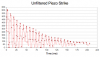
You showed a graph of an unfiltered 12Hz piezo strike that has time on the horizontal but simple numbers on the vertical. Are the numbers the voltage? The vertical has a DC offset. Where does the DC come from? A piezo does not produce a continuous DC offset like that, instead its output is AC that swings positive and negative.
Does your opamp buffer for the piezo have a needed DC reference voltage?
Doesn't the output of the piezo swing positive and negative? Then what will prevent the negative swings from damaging the input of the buffer opamp that does not have a negative supply?
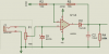
Here is the schematic of an e-drum peak detector. It uses one opamp in an LM324 (one opamp in an LM358 is the same) that has a single positive supply and has inputs and an output that work down to 0V.
1) The 100k volume control provides a DC reference input voltage of 0V.
2) The Schottky diode D1 prevents the input voltage from swinging negative which would zap the opamp.
3) The C2/R4 output determines the duration of the DC peak output voltage.
You showed a graph of an unfiltered 12Hz piezo strike that has time on the horizontal but simple numbers on the vertical. Are the numbers the voltage? The vertical has a DC offset. Where does the DC come from? A piezo does not produce a continuous DC offset like that, instead its output is AC that swings positive and negative.
Does your opamp buffer for the piezo have a needed DC reference voltage?
Doesn't the output of the piezo swing positive and negative? Then what will prevent the negative swings from damaging the input of the buffer opamp that does not have a negative supply?
Here is the schematic of an e-drum peak detector. It uses one opamp in an LM324 (one opamp in an LM358 is the same) that has a single positive supply and has inputs and an output that work down to 0V.
1) The 100k volume control provides a DC reference input voltage of 0V.
2) The Schottky diode D1 prevents the input voltage from swinging negative which would zap the opamp.
3) The C2/R4 output determines the duration of the DC peak output voltage.
Attachments
BobK's suggestion of the MCP6001 should work. Make sure you get the PDIP version for ease of use. They are available from Mouser Elecrtonics. Failing that you could use my original suggestion of the CA3140 again the PDIP version. They are also available from Mouser as well as Newark Electronics
The CA3140 is at lesat $2 a piece and I would need 24, would this be any faster, more accurate?BobK's suggestion of the MCP6001 should work. Make sure you get the PDIP version for ease of use. They are available from Mouser Elecrtonics. Failing that you could use my original suggestion of the CA3140 again the PDIP version. They are also available from Mouser as well as Newark Electronics
- Joined
- Jan 21, 2010
- Messages
- 25,510
would this be any faster, more accurate?
What's the gain bandwidth product of the CA3140 compared with the MCP6001? Is the difference significant?
Is there an equivalent to the MCP6004 for the CA3140?
What do the datasheets say?
And of course, what are you actually trying to do? Because your initial statement you wanted a peak and hold appear not to be the case.
Does your drum produce radio frequencies?
One opamp has a gain bandwidth of 1MHz (middle of the AM broadcast band) and the other is 4.5MHz on the shortwave band.
I think you are making an electronic piano like my kids had 30 years ago but theirs used pushbuttons tp play the notes and yours uses piezos that are struck.
One opamp has a gain bandwidth of 1MHz (middle of the AM broadcast band) and the other is 4.5MHz on the shortwave band.
I think you are making an electronic piano like my kids had 30 years ago but theirs used pushbuttons tp play the notes and yours uses piezos that are struck.
Similar threads
- Replies
- 10
- Views
- 2K