being a newbee i am not sure i was expecting 0volts
It won't be 0V, and that much should be obvious.
OK, maybe not obvious
")
When the output is at logic 0, the voltage on the output is typically close to 0V. When the logic level is 1, the output voltage is close to the supply rail.
But it's more complex than that. Different types of logic have a different range of voltages that are valid for a logic 1 and a logic 0. Depending on how these logic circuits are made, the outputs may or may not get really close to the supply rails. TTL (or LS TTL that you're using) is an example of a logic family that often can't get especially close to the positive supply rail.
So let's assume that the 4V you read on the enabled output is close enough to the +ve supply (which is probably 5V) for us to just call it the +ve supply. And if it was logic 0, let's assume the voltage is effectively 0V.
The output of normal logic is somewhat akin to having two little people with ropes who try to pull the output close to their respective voltage rail. When the output is set to 1, the man on the bottom lets his rope go slack and the man on the top pulls on his rope and the output goes high. When the output is 0, the man on the top lets his rope go slack and the man on the bottom pulls on his rope to take the output low. Importantly, those little men don't pull on their ropes at the same time, but in normal logic one man is
always pulling on a rope..
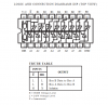
This chip is a bus driver. It is designed to have many outputs connected together so that any of them can place a signal on the common bus. That signal could be a logic 0 or a logic 1.
If we connect many of these outputs together, all is fine if all are at logic 1, because all the men on top will be pulling their outputs (and thus the bus) up, or all are at logic 0 because all the men on the bottom are pulling their outputs (and thus the bus) low.
But the idea of a bus is that any gate can place a signal on the bus. Let's assume all the gates are low, and one gate decides to pull its output high. In this case the man on the bottom lets his rope go loose, and the man on the top tries to pull the output up. However that one man on the top finds he is pulling against many other little men on the bottom. Several things can happen:
- The man on the top tries, but can't pull hard enough
- The man on the top pulls really hard and breaks his rope
- The man on top pulls so hard, and with a strong enough rope that he breaks all the other bottom man ropes.
- The man on the top pulls really hard and overpowers all the men on the bottom.
None of these are really good. Anything where a rope breaks would be a failure in a chip that would need to be replaced. Either of the overpowering scenarios isn't good either because it depends on how many are pulling in the other direction, and all the expended effort will make the chips get hot.
The obvious solution in the little men case is to allow both little men to let their ropes go slack. If all of the outputs are in this state, and one output decided to enable it's little men and pull it's output high or low, the bus will follow and so will the outputs that are connected to it. The ropes are slack, so a slight pull from one top or bottom man is able to pull all the other outputs high or low.
Both ropes being left slack is one method of implementing a tri-state output.
Now, of course, these are no little men in logic chips, but there are transistors doing exactly what those little men do, and instead of ropes they have a low impedance state which pulls the output to the matching supply rail. In this case, one transistor (little man) is in a low impedance state (pulling on the rope) and the other transistor (little man) has a high impedance state (slack rope). The output goes toward the low impedance. Tri-state can be implemented as having both transistors go into the high impedance state (so the output is not pulled strongly either way). This is why is is also called a "high impedance" or "High-Z" (Z is the symbol for impedance) state.