I would run the strain gauge off 5V, the AD620 off 9V. That would put
40 mA thru strain gauge, what was the max allowed current ?
If thats too much current power off 9V with a series R to limit current
to spec. Or use a low voltage zener. This all has to be simed out to see
what range you get into A/D. Ideally A/D would see 0 - 5V or something
like that. Depends on how unbalanced the starin gauge is in application.
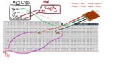
So I would run the strain gauge off 5V with a series R of 120 ohms to its
+ power lead. Thats 20 mA thru bridge. Then use diamond tool to find
what Vref you need and G setting for 620 to get 0 - 5V out of it. For a +100
mV deviation in the bridge and 0V for a -100 mV deviation.
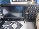
Great scope, so in display mode set it to AC, 1V / div, infinte persistence, sweep
rate of say 1 mS / div, norm trigegring, trigegr set to edge, say 50 mV, and what do
you get for peak to peak noise. Let it run in that mode for a minute or two before
you take the visual reading.
You need to set the G, not with a pot, but a fixed R. So we have
a design deviation of +/- 100 mV, and we want the slope of a straight
line into A/D, when at +100 mV, to generate 5V. So what is that G ?
Remember you are working with a straight line transfer function with an offset.
These settings interact with each other. But we know how to fix the G, discussed
above, now we have to get the offset right.
I am going to leave for awhile, get a pic of your power supply adapter output.
Many of those crappy supplies have a minimum load requirement to stay in
regulation and keep noise down. So examine it with scope.
You want a clean, low noise, say 100 mV or less out of it, and ~ the value you
are seeking.
I did a sim, but AD620 spice model has a problem allowing a connection
to Vref pin. So I have contacted Analog Devices to see if I can get this
rectified.
I did a sim, but AD620 spice model has a problem allowing a connection
to Vref pin. So I have contacted Analog Devices to see if I can get this
rectified.
Do a simple test, no arduino, just module and a small V into module inputs :
Replace above probe with your module inputs, and set its G to 10, and use
the diamond tool to predict, for the Vref you have, what output should be,
and compare that with what the test gives you.