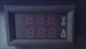
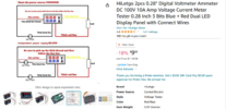
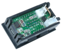
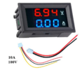
I attached a screenshot of the voltmeter and a diagram of it.
The diagram shows all you need.
If the voltage you want to measure is > 4 V (and < 30 V), use the top diagram ("Share the power supply"). The supply power for the module will then be taken from the voltage source you measure.
So I assume you are using the meter mainly on 12 V, with the variablke power supply going down to maybe ~ 6 V to test circuits at very low voltage. In this case the connection as noted above is fully usable.
It will cease working only when you go below 4 V.
If operation
below 4 V is required (and only in that case), then you need a separate power supply for the module. Connect it as shown in the lower diagram ("Independent power supply").
you mean like a 9 volt battery?
Possibly, but a 9 V battery will be drained rather quickly by the module (since the module uses an LED display, power consumption is comparatively high). A USB power bank at 5 V may last longer and is rechargeable. Or your variable power supply might have a separate voltage output, idk.
I figured with all the technology they
would have figured something better out by now.
Define "better".
A unit that in many cases doesn't need a separate power supply is not bad. It is also a physical necessity to provide power to the unit and this will require a minimum input voltage (4 V in this case). There's nothing wrong with that.
One surely could build a unit that draws less power using e.g. an LCD instead of the LEDs, then add a step-up power supply regulator, possibly an internal battery and/or some energy harvesting circuitry to span times when no external power is present etc. etc.
Is that better? It is definitely much more expensive and this will have many users deny the "betterness" of such a module.
")