555 circuit to open/close car door window

burrism

Oct 15, 2024
14
Joined
Oct 15, 2024
Messages
14
Hello. I have an Arduino board and circuit that I am using to open/close my car door window based on the door being opened or closed but it is a current drain. :( I am hoping someone can assist with a 555 timer circuit that i can use to replace my battery killing PIC.

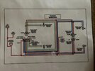
Door opens, switch closes (and stays closed) and the 555 circuit powers a MOSFET or relay to lower the window for 0.5 sec
Door closes, switch opens (and stays open) and the 555 circuit powers a MOSFET or relay to raise the window for 1.0 sec.

Thanks!
 

Delta Prime

Jul 29, 2020
2,989
Joined
Jul 29, 2020
Messages
2,989
I have an Arduino board and circuit that I am using to open/close my car door window based on the door being opened or closed but it is a current drain
Welcome to Maker Pro.
Arduino board? UNO maybe?
Here’s a little snippet from the below link.
Sleep modes, use of power-reduction registers, and other techniques. Applying all of them can result in a current draw as low as approximately 100 nano-amps (100 nA), well below the self-discharge rate of most batteries.
IMG_0066.png
from the data sheet for the Atmega328P page 405
https://www.gammon.com.au/power

Example of High side MOSFET driver for your window/door
IMG_0067.png
 
Last edited:

Alec_t

Jul 7, 2015
3,817
Joined
Jul 7, 2015
Messages
3,817
A problem with using fixed times for the open/close electronic functions is that friction in the movement mechanism will change the window speed with e.g. temperature, moisture present, dirt on the glass etc. You would also need sensors to detect obstructions (pet's head, kid's fingers etc) and the fully open/closed states.
 

burrism

Oct 15, 2024
14
Joined
Oct 15, 2024
Messages
14
A problem with using fixed times for the open/close electronic functions is that friction in the movement mechanism will change the window speed with e.g. temperature, moisture present, dirt on the glass etc. You would also need sensors to detect obstructions (pet's head, kid's fingers etc) and the fully open/closed states.
Sir - yes those can be issues but my kids are in the 20s, my dog has hair and it is for my 59 impala. I use this to save the door seals as the glass goes right into the weatherstrip on the top of the opening. The timing is not as important as the function and so far I have not had any issues with debris or moisture.

Thanks for the thought tho.
 

burrism

Oct 15, 2024
14
Joined
Oct 15, 2024
Messages
14
Welcome to Maker Pro.
Arduino board? UNO maybe?
Here’s a little snippet from the below link.
Sleep modes, use of power-reduction registers, and other techniques. Applying all of them can result in a current draw as low as approximately 100 nano-amps (100 nA), well below the self-discharge rate of most batteries.
View attachment 64984
from the data sheet for the Atmega328P page 405
https://www.gammon.com.au/power

Example of High side MOSFET driver for your window/door
View attachment 64985
Thank you sir. I will have to dig into those options and see what I can do. I have an Arduino Nano (and it is probably a knock-off).
 

AnalogKid

Jun 10, 2015
3,047
Joined
Jun 10, 2015
Messages
3,047
Does not sound difficult.

But . . .

To design a drop-in replacement, it is kinda important to see what you are dropping into. Please post a schematic / sketch / cocktail napkin of your complete circuit as it is now. Power connections, transistors, switches, motors, a block for the Arduino - everything.

ak
 

burrism

Oct 15, 2024
14
Joined
Oct 15, 2024
Messages
14
Does not sound difficult.

But . . .

To design a drop-in replacement, it is kinda important to see what you are dropping into. Please post a schematic / sketch / cocktail napkin of your complete circuit as it is now. Power connections, transistors, switches, motors, a block for the Arduino - everything.

ak
So here is what I have regarding the Arduino but I would like to explore options that do not require a PIC.
 

Attachments

  • seal saver schematic v2.pdf
    70.4 KB · Views: 6

AnalogKid

Jun 10, 2015
3,047
Joined
Jun 10, 2015
Messages
3,047
The Q1 and Q2 emitters don't go anywhere. The both should be grounded.

Is the goal of the project to replace the Arduino with a circuit, but the circuit drives the same two relays? If yes, then we need part numbers / coil currents for the relays.

The relays probably can be replaced with poser MOSFETs, but we need to see all connections to whatever UP and DN are - Everything from the battery to the devices to GND. Are these two separate motors, or what? From the schematic, we can't tell if MOSFETs would be pulling one end of a load up to +12, or down to GND.

Also, what is the signal "Input" that the jamb switch is shorting to GND? What is the open-circuit voltage?

ak
 
Last edited:

AnalogKid

Jun 10, 2015
3,047
Joined
Jun 10, 2015
Messages
3,047
As a first-pass, here is something from about nine years ago on another forum, tweaked for your application. Click on the image for a larger image. Standby current is in the low microamp range.

R1-C1 is a noise filter.

R2-C2 and R3-C3 are the two output pulse timers. The component values are approximate for your times.

This circuit shows MOSFETs driving relays. Depending on your exact car wiring, you might be able to eliminate the relays.

ak

DualPulser-8-c.gif
 
Last edited:

davenn

Moderator
Sep 5, 2009
14,474
Joined
Sep 5, 2009
Messages
14,474
A problem with using fixed times for the open/close electronic functions is that friction in the movement mechanism will change the window speed with e.g. temperature, moisture present, dirt on the glass etc. You would also need sensors to detect obstructions (pet's head, kid's fingers etc) and the fully open/closed states.
Sir - yes those can be issues but my kids are in the 20s, my dog has hair and it is for my 59 impala. I use this to save the door seals as the glass goes right into the weatherstrip on the top of the opening. The timing is not as important as the function and so far I have not had any issues with debris or moisture.

Thanks for the thought tho.

You also need end of travel ( limit) sensor switches for when the window is fully open or closed ....As Alec_t said, you cannot use travel timing
 

Delta Prime

Jul 29, 2020
2,989
Joined
Jul 29, 2020
Messages
2,989
Thank you sir. I will have to dig into those options and see what I can do
No problemo! That’s why we are here…
Along with the hair of the dog that bit me! I’m pretty sure it was a dingo!
:D
 

AnalogKid

Jun 10, 2015
3,047
Joined
Jun 10, 2015
Messages
3,047
I should have put this in #9, but now I can't. Three things.

1. Having one 555 monostable circuit make two different pulse widths is not impossible, but takes many external parts. And, you need more parts to steer the one output to two different output devices (MOSFETs, relays, motors, whatever).

2. To trigger two 555's, one from the input signal leading edge and one from the trailing edge, requires an external inverter circuit to correct the Trigger edge direction for one of the 555's.

3. The CD40106 is a CMOS hex inverter with Schmitt trigger inputs. It is six independent inverters in a single 14-pin package.

ak
 

burrism

Oct 15, 2024
14
Joined
Oct 15, 2024
Messages
14
The Q1 and Q2 emitters don't go anywhere. The both should be grounded.

Is the goal of the project to replace the Arduino with a circuit, but the circuit drives the same two relays? If yes, then we need part numbers / coil currents for the relays.

The relays probably can be replaced with poser MOSFETs, but we need to see all connections to whatever UP and DN are - Everything from the battery to the devices to GND. Are these two separate motors, or what? From the schematic, we can't tell if MOSFETs would be pulling one end of a load up to +12, or down to GND.

Also, what is the signal "Input" that the jamb switch is shorting to GND? What is the open-circuit voltage?

ak

Awesome response, really making me think and remember all at the same time!

Yes, the idea is to replace the Arduino with a circuit. I currently am using MOSFETs to drive a 5v relay to complete the circuit to open/close the window. I chose to add relays to the circuit in addition to MOSFETs because the motors can easily draw 10A when activated (12v car circuit has 20A fuse for the windows). The relays can handle up to 30A and I do no need to pass ground or any voltage so I cannot just use a MOSFET (given my limited MOSFET knowledge).

Currently the window switch, when closed, send 12v to one side or the other of the motor. A sample diagram of a typical power window is attached.

The door jamb switch currently passes chassis ground to the dome light when the door is opened. I would like to use the same switch but realize I may not be able to as the ground being passed isn't just ground once the switch closes. So I am not opposed to adding another switch specifically for this purpose. Link to switch.

Regarding the up and down time, I am hoping someone can elaborate why I cannot use timing to control the UP and DOWN. I am just looking to crack the window to relieve overpressure then put it back up. As you can see in the power window kits available, there are no limit switches or sensors to register full UP or DOWN, just the user stopping the input (and one NEVER stops the window exactly when it reaches the UP position). My intention is to emulate that by doubling the UP time (down 0.5 sec and up 1.0 sec)

I am slowly catching up on the rest of the comments and drawings.
 

Attachments

  • 2304140030_Ningbo-Songle-Relay-SLA-5VDC-SL-C.pdf
    83.6 KB · Views: 2
  • power window schematic.JPG
    power window schematic.JPG
    216.4 KB · Views: 2

Bluejets

Oct 5, 2014
7,374
Joined
Oct 5, 2014
Messages
7,374
Hello. I have an Arduino board and circuit that I am using to open/close my car door window based on the door being opened or closed but it is a current drain.
One has to ask is this an "add-on" modification to the vehicle as standard fitment would have all the necessary equipment such as limits and switching already in place.
 

Bluejets

Oct 5, 2014
7,374
Joined
Oct 5, 2014
Messages
7,374
The door jamb switch currently passes chassis ground to the dome light when the door is opened. I would like to use the same switch but realize I may not be able to as the ground being passed isn't just ground once the switch closes.
Yes it is.
 

burrism

Oct 15, 2024
14
Joined
Oct 15, 2024
Messages
14
One has to ask is this an "add-on" modification to the vehicle as standard fitment would have all the necessary equipment such as limits and switching already in place.
Much like the power windows, this is totally an add on "feature". You can view the vehicle here
 

burrism

Oct 15, 2024
14
Joined
Oct 15, 2024
Messages
14
Yes it is.
Sure, technically it is. However, the impedance of the circuit goes way up once the switch is closed which could cause issues detecting open or closed. I am not sure how to address that with something that is not a PIC. I have an impedance level set in my Arduino code to be above 300 to help with this potential issue. But then again, an additional switch would alleviate the issue.
 

burrism

Oct 15, 2024
14
Joined
Oct 15, 2024
Messages
14
I should have put this in #9, but now I can't. Three things.

1. Having one 555 monostable circuit make two different pulse widths is not impossible, but takes many external parts. And, you need more parts to steer the one output to two different output devices (MOSFETs, relays, motors, whatever).

2. To trigger two 555's, one from the input signal leading edge and one from the trailing edge, requires an external inverter circuit to correct the Trigger edge direction for one of the 555's.

3. The CD40106 is a CMOS hex inverter with Schmitt trigger inputs. It is six independent inverters in a single 14-pin package.

ak
AK - thanks for all the information, definitely getting in over my head. I figured/guessed that my circuit would be 2 smaller 555 circuits, one for each action.

But you lost me on the external inverter circuit... The only things I could find on the web about an inverter circuit were about making 220v from a 12v battery (or similar).
 

AnalogKid

Jun 10, 2015
3,047
Joined
Jun 10, 2015
Messages
3,047
Logic inversion, not power inversion.

The 555 Trigger input responds to a negative edge. In a 12 V circuit, when the signal driving the Trigger input transitions from a voltage greater than 4 V to less than 4 V, the output goes high for the timing period. *** When the door opens and the switch closes, the signal goes from 12 V to 0 V (-ish), 555 #1 is triggered, and everyone is happy.

But

When the door closes, the Trigger signal goes from 0 V to 12 V. This is the wrong direction to trigger the second 555. You need an additional small circuit to turn this positive-going edge into another negative-going edge for 555 #2. This can be as simple as 1 small-signal NPN transistor plus 2 resistors.

In my schematic #9, notice that the upper path has one inverter (U1B) driving the differentiator, but the lower path has two inverters (U1F plus U1E) driving its differentiator. U1E is doing the same thing as as described above, changing which edge the pulse circuit responds to.

ak

*** Actually, there is a problem with that. The standard monostable circuit in a 555 datasheet is not a *true* monostable, because the output period is not completely independent of actions at the Trigger input. If the door stays open for longer than the timeout period (0.5 s in your case), the 555 output will not go low and the motor will continue to run until the door is closed. This is a well-known 555 issue, and so is the fix, but the point is that there is a bit more to a two-555 solution than you think. I can expand on this if you want.
 
Last edited:
Top