is installing a step down transformer a diy project?

noquacks

Jun 26, 2013
148
Joined
Jun 26, 2013
Messages
148
People,

This may be more "electrical" and not "electronics", but here it is:

Have a 251V outlet to service a component that cannot take more than 240V. I heard of buck-boost, and step down, but is it a simple task to but a transformer, and plug it in, to step down to the max of 240V that the equipment needs? The power company said their power is "correct", and because they have a 5% + or - the 251 is within. Tuff luck for me. Sheesh.

Where would one start? There are many types available on Amazon, for example.

Advice appreciated. Thanks, people.
 

Bluejets

Oct 5, 2014
7,374
Joined
Oct 5, 2014
Messages
7,374
Mostly it would be ok but as we have no idea just what this "equipment" comprises, what current draw, what tolerances are imposed by the manufacturer, then it's anyones guess.
5% supply variation is a fairly standard supply authority spec.
Depending on the country naturally, as example, Thailand can drop to 180 and it's considered as just good luck that you get anything.
Are you actually getting 251v under load or just the printing on the outlet? 251v is an odd number. Or is the supply authority transformer sitting on your front porch?

I believe you are overthinking the situation.
 
Last edited:

Bluejets

Oct 5, 2014
7,374
Joined
Oct 5, 2014
Messages
7,374
Jesus Christ really?what load of blue jet crap. I mean happy holidays and Merry Christmas. Do you still live in Florida,United States?
The AC voltage is stated are RMS values and the plus or -5% is the quality factor for your utility company and this is all correct.

Buck-boost is a DC to DC voltage converter.
Buck; DC to DC step down converter.
Boost; DC to DC step up converter.
A DC to DC buck- boost converter can do both.
Not on AC mains.
 

noquacks

Jun 26, 2013
148
Joined
Jun 26, 2013
Messages
148
Thanks, people. I have work to do on this! Not as simple as I figured.
 

73's de Edd

Aug 21, 2015
3,730
Joined
Aug 21, 2015
Messages
3,730
Sir No Quacks . . . . .
I am perceiving that this is being the point in this evolving thread to . . . . . . . . insert my entry . . . . . .so here goes. Without my consulting that Florida, power and light crappiola . . . .now . . . . .stand way back.
I see that your desired 240VAC incoming AC line power can permissibly soar upwards from 240VAC . . .or NOW, ACTUALLY is already being 251VAC.
So now . . .ideally . . . .you want to only present LESS THAN that menacing 240 VAC into your, now connected' "touchy-touchy-feely-feely-delicate " instruments AC input power wiring.
You can effectively accomplish that feat by merely inserting a small (filament/control transformer in series with the hot wire of the present AC line input .
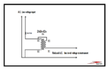
Submitted herewith, is a schematic representation of the manner of your accomplishing that.
( Mouse . . . . . LEFT CLICKEE-CLICKEE . . . .SHO' NUFF MAKES MO' BIGGIE !
Circuit walk through . . . . . the daisys
AC line power enters at the top and the left, where the neutral line initially drops down to feed terminal B of the small power transformer primary and further on to the right to be the outputted neutral line of the outputted/ reduced / corrected AC voltage for your instrument..
Refer to the top AC inputs second HOT line that flows down to an inserted series power switch, so that power will not be on the power transformer
primary terminal A during usual times of non use.
Now note that HOT 251VAC is routed over to the right and is connected to the secondary C wire of the transformer secondary, which will let power flow in C and out D wire.
What you want to do next is measure the AC voltage outputted at the output arrows. That transformer secondary, being in series, can add its voltage or diminish it . . . . . . in accordance to how you connected the C and D wires out of .if you read on upwards of 260'ish+ AC volts you are in series aiding connectivity of two series phase related voltages . . . .not being what you want.
So you need to reverse/swap C and D wires connections . That will have the secondary phase bucking its voltage and get you down to your more desired251 minus 12 to 239ish AC voltage . . . . . .or actually a bit lower since you are hitting that transformer primary harder at 251VAC and getting more that 12VAC out, if powered with a lower 240VAC input.

Now one other factor I will throw in . . . . . .was the fact that you made no mention of the INSTRUMENTS power consumption .
With my making a guesstimated HIGH wattage consumption of 250W that would have 1 amp flowing to that instrument . So select a 12Vvac @ 1 amp transformer secondary to be used .
 

Attachments

  • 1743740813720.png
    1743740813720.png
    23.4 KB · Views: 7
Last edited:

73's de Edd

Aug 21, 2015
3,730
Joined
Aug 21, 2015
Messages
3,730
POST . . .time cut off limit . . . . . .EDIT
So now . . .ideally . . . .you want to only present LESS THAN that menacing 251 VAC into your, now connected' "touchy-touchy-feely-feely-delicate " instruments AC input power wiring.
 

Externet

Aug 24, 2009
943
Joined
Aug 24, 2009
Messages
943
1.- How healthy / accurate is your voltmeter ? Tried another ?
2.- I do have 251VAC at my house, and probably at near neighbors too, as my inverter feeds the roof solar panels excess production back into mains grid. Any neighbors with solar generation near you ?
 
Last edited:

poormystic

Jul 23, 2023
187
Joined
Jul 23, 2023
Messages
187
Hi noquacks:)
The power supply correction you say you require can be made using a Variac, or adjustable autotransformer. For a 1kW Variac you might pay $500 or so I guess.
Mark
 
Top