Technics SU-X102 amp repair, asking for guidance

Orloj

Jan 22, 2025
11
Joined
Jan 22, 2025
Messages
11
Hi, I recently acquired a Technics sound system from the 90's, including the su-x102 as its amplifier.
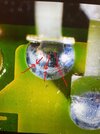
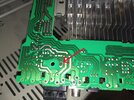
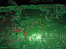
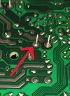
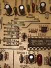
Sadly it is faulty (I bought it knowing that, don't worry), when I tried turning it on the front panel wouldn't work and it would be amplifying noise on the treble line. Somehow the eq controls on the front worked as I could make the noise louder or quieter by turning the treble pot. The guy who sold it to me told me "when this happens, smack it on the side and it'll turn on" which made me feel a little hesitant but it worked. It worked for a whole 20 seconds before the two transistors in the system burned off. (white smoke and everything) After checking, it seems like no other components died luckily. At least my naked eye spotted nothing visibly wrong.

So, here's the few things I noted from this happening :
- the front panel "works", at least for the short time the system worked
- the main amplifier component works since it amplified the noise
- the outputs work

So basically everything was working fine, except I'm guessing I had a short somewhere that I'm yet to have found
Can anyone help me troubleshooting that please ? I only have a multimeter for this task

Bonus point if you can help me find where to buy replacement transistors, the ones I burned are the 2S5B1187DEF and 2SD1761DEF
(I'm located in Europe)

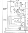
Here you can find the service manual with all the part numbers and schematics (Internet Archive)

Thank you for reading
 

ahsrabrifat

Jan 18, 2025
76
Joined
Jan 18, 2025
Messages
76
Use your multimeter to check for continuity and proper resistance values across components. Thus you can identify any open circuits or components that may have failed.
 

Orloj

Jan 22, 2025
11
Joined
Jan 22, 2025
Messages
11
Use your multimeter to check for continuity and proper resistance values across components. Thus you can identify any open circuits or components that may have failed.
Checked everything and here's my observations :
all the resistors are good, and values are within range
most ICs are good except for the IC503 (toshiba tc4066bp) which has its pin 14 having continuity with gnd whereas the schematics say it should be +6v, but if you follow the traces there it does end up to the gnd so... i genuinely don't know
the transistors that died (Q703 Q704) also seem to not be shorted somehow ??? some of their pins have continuity with gnd but its according to the schematics so idk

i have no idea whats wrong with my amp, what else can i do ?

attached a capture of the IC that seems a bit iffy if anyone can tell if its wrong or not

edit: AC has continuity with GND, forgot to mention it but i'm guessing its supposed to be this way ?
 

Attachments

  • Capture d'écran 2025-01-24 231710.png
    Capture d'écran 2025-01-24 231710.png
    419.3 KB · Views: 4

H2814D

Nov 4, 2017
258
Joined
Nov 4, 2017
Messages
258
Supply clear photos of the component boards, and if you are able, both side of the boards, so we can see what you are looking at.
 

Orloj

Jan 22, 2025
11
Joined
Jan 22, 2025
Messages
11
Here's pics of the front of the board, i'll put the back in a separate message

board_full.jpg

power_supply.jpg

acs.jpg

primary_amp.jpg

main_amp.jpg

where_it_burned.jpg
 

H2814D

Nov 4, 2017
258
Joined
Nov 4, 2017
Messages
258
I hope the pics aren't too blurry
The pics are fine for now. So hearing that the previous owner mentioned that slapping the side of the unit would make it come on leads me to believe there may simply be failed solder joints that need to be looked for. Another thing is that that unit has a substantial number of electrolytic capacitors installed in it. Based on the design of the board, the age of that particular model, and where it was made (Japan), could also mean that some of the capacitors may have reached the end of their useful lives.

I would first start by examining each one of the solder joints on the bottom of the boards you have there, paying particular attention to anywhere there are larger ground point solders and power supply wiring and connector solder joints. And also look at the components pins on the board that are attached to heat sinks. What you will be looking for are what is called "cold/cracked solder joints." I don't know how much you know about what those are, or what they look like, but if not, there are several videos and photos available for you to look at by running those words in a search engine. I attached a pic of one here too. I also attached a marked copy of what may be one from your supplied pics, but at least you will know what to look for.

What happens to those solder joints is, during the operation of the unit, the solder joints where the power supply currents and components that heat up during use are, eventually cool back down when the unit is powered off. The constant heating and cooling of the joint eventually causes very small cracks to occur in the solder, which affects their performance. You can usually see them with a magnifying glass, and sometimes, if they are large enough, without one. But do that examination first. If you find any that are suspect, reflow (remelt) the solder with a soldering iron and add additional solder, if necessary.

The next step would be to check the capacitors. If you don't have an ESR Meter, you will have to check each one by pulling at least one pin from each one out of the circuit.

Let us know what you find.
 

Attachments

  • Cracked Solder Joint.jpg
    Cracked Solder Joint.jpg
    125.4 KB · Views: 14
  • IMG_20250125_153301.jpg
    IMG_20250125_153301.jpg
    425.5 KB · Views: 13
  • IMG_20250125_153231.jpg
    IMG_20250125_153231.jpg
    481.2 KB · Views: 12
  • IMG_20250125_153257.jpg
    IMG_20250125_153257.jpg
    58.8 KB · Views: 13

Martaine2005

May 12, 2015
5,276
Joined
May 12, 2015
Messages
5,276
@H2814D said everything that I was going to say.
There does appear to be quite a few dry solder joints over the board. But it could also be lighting and shadow.
 

Delta Prime

Jul 29, 2020
2,987
Joined
Jul 29, 2020
Messages
2,987
Bonus point if you can help me find where to buy replacement transistors, the ones I burned are the 2S5B1187DEF and 2SD1761DEF
I’m all about bonus points!
Along with being on double secret probation!
The DEF portion of the part number can be dropped. It’s a categorization of DC current gain “hFE”
They are compliments of one another.
both are bipolar transistors but one is NPN. The other is PNP respectfully.
Below photo is only an example.
Shop around for best price, you might get one even cheaper…
IMG_0234.jpeg
 

Orloj

Jan 22, 2025
11
Joined
Jan 22, 2025
Messages
11
So huh, i have no idea how to measure caps without an ESR but i figured it wouldn't hurt to just swap all the old caps on the motherboard
Lucky me, i found a local supplier (literally at the city next to me) that is super cheap
Found all the big caps except the two 50v 1000pf on the main amp, so i hope those aren't defective
Ah also, there is a 55v 330uf one that i couldn't find a replacement for, so i bought a 63v. Should be fine right ?
Capture d'écran 2025-01-31 175636.png
 

Orloj

Jan 22, 2025
11
Joined
Jan 22, 2025
Messages
11
PS: once this all arrives, i'll to the replacements, redo all the bad solders i can notice and report back to you guys
 

Martaine2005

May 12, 2015
5,276
Joined
May 12, 2015
Messages
5,276
The voltage is fine when higher, never lower.
(Unless of course a 55V cap is in a 12V circuit. Which of course, a 16V (at a push) but generally a 25V or higher capacitor can be used.
 

Orloj

Jan 22, 2025
11
Joined
Jan 22, 2025
Messages
11
So hum, little issue im noticing
Im currently swapping the caps and while the service manual says for exemple c708 should be 16v 100uf, the one that is on the board is a 6.3v 47uf... wtf is this ? im going with what the manual says but i really hope its not gonna explode on me
 

Orloj

Jan 22, 2025
11
Joined
Jan 22, 2025
Messages
11
Okay so extra problem, while desoldering the two burnt transistors, 2 traces of the first one broke off
will have to fix that with wires
 

Orloj

Jan 22, 2025
11
Joined
Jan 22, 2025
Messages
11
IMG_20250206_193556.jpg

My sincere apologies for the warcrime of a soldering job this is. The rest of my solders are way better but i did what i could with the broken traces
edit: the flashlight makes it look way worse than it actually is
 

Orloj

Jan 22, 2025
11
Joined
Jan 22, 2025
Messages
11
After plugging the unit and turning it on, the front panel works perfectly (nice!) but i was hearing an awful lot of noise, also a diode burned ? YET ANOTHER PIECE TO DIE ??? ... wtf is going on
 

Attachments

  • IMG_20250206_213638.jpg
    IMG_20250206_213638.jpg
    361.7 KB · Views: 6

Delta Prime

Jul 29, 2020
2,987
Joined
Jul 29, 2020
Messages
2,987
No need to for profanity.Q1 max smoke as well.
a soldering job
1738894024488.png

All the discreet components are way past their operational lifespan. It’s a cascade effect you are encountering even the traces & solder pads themselves are degraded. you have made a valiant effort, but fear you will still continue. You are committed in purchasing those components, but in time you will realize your task is futile. Time of death 6:21 PM my condolences..
 
Top