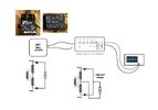
I'm planning to measure the HV output waveform from an NST using a 1000:1 potential divider, which is yet to be built, and I have a few queries about the measurement setup. I have included a diagram of the proposed design and arrangement and where the small NST has a stated output of 1.5kV RMS.
My main query is regarding the effect of the assumed centre tap of the NST on the measurement setup. As I understand it, if the output is 1.5kV RMS, then the two output cables provide + and - 750V RMS AC. However, if I connect both cables to the single + input of the divider, that will surely constitute a short for the NST and shut it down. If I don't connect the second cable then I have a floating ±750V. I don't know if the NST has diodes as my suggested circuit shows, but if there were then that might also change matters.
The second issue is that this third-party divider design does not have a negative or ground line on the input side but, if needed, I presume one can link the negative on the low-voltage output side to the ground of the input source? In the case of the NST I am using, the only ground line would seem to be the centre tap, which must be connected in this case to the DC supply ground, but this device does not provide an external connection to that, although I understand that many NSTs do provide a connection to the usual AC supply ground.
I would appreciate any advice.
Thanks
")
