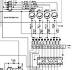
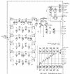
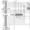
Ok. Just spent some time scouring the schematics. RF board sends the band switch lines for each band, 160, 80,40,30,20,17,15,12,10 to the Local board Local board send them to the LPF, but it combines 12 and 10 in one, and 17 and 15 into another. 30 and 20 into a 3rd and the rest are by themselves. There are 6 LPF's The signals are combined by diodes. I've seen a lot of youtube videos where they replace them for a lot of reasons, some they replaced them "just because". The factory diodes have a 10V reverse breakdown voltage rating... in a radio powered by 13.8 volts. The 1N4148's they use have a 75V reverse breakdown voltage I'm thinking the ones that pass the 12 and 17M signals are open. since I'll have the board out, I may as well change them all to alleviate issues in the future. I've attached the sections of the schematics showing them...
Going to attack this in the morning...
")