Jeroensprint
- Mar 17, 2026
- 5
- Joined
- Mar 17, 2026
- Messages
- 5
Hello, Englisch is not my native language but I will try to explain. I have made a reversing circuit with four relays for the pop-up headlights of my son's car. With it, he can make one light wink. It is a simple circuit what does work on paper. The schematic isn’t the problem or how to connect. Originally, when the lights are open, a constant voltage of 12 volts remains on a wire to the headlight motor, and when the lights are closed, that voltage drops and switches to another wire to the headlight motor so that the headlight closes again. This voltage switches back and forth via an original switch. With relays, I reverse these voltages for a headlight so that one headlight briefly receives its voltage in reverse, causing it to wink/open or close independently from the main system.
When I press my relays into the sockets, both lights start opening and closing uncontrollably without touching anything, and without there even being a switch or wiring in the socket to energize the relays. The relays do not click and, as mentioned, can never be energized from the outside because that wiring is not yet attached. There are four relays for one headlight that connect in the resting position. Connect all 30s to 87as in the resting position to maintain the original headlight control in normal driving conditions. If I simulate the relays in the resting position and create wiring loops and press these into the relay sockets between the 30s and 87as instead of the relays, the headlights work without problems.
I discovered that while measuring with the relays mounted, using a voltage tester with a light to see exactly what was happening, as soon as I hold a voltage tester against any wire (30 or 87a) in the socket, the circuit (connection in the resting position) works.
I tried a different brand of relay and also separated the sockets to create space between the relays, in case they were influencing each other in that way, but the result was the same.
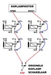
The picture shows part of the circuit as it is now. With the relay this strange fault appears, and with the relay removed and bypassed with wire in the relay sockets (blue in the drawing), the normal original control works. Does anyone know what is going on here?
The problem is maintaining the car's ‘original wiring’: lights on, headlights up; lights off, headlights down, or via the external original pop-up headlight switch. If I connect the 'original wiring' via relays, I get this strange fault, but if I connect it in the socket with a wire loop, it works just fine.
Why does a relay in the resting state, with 30 and 87a internally connected, behave differently here than just a connecting wire in it’s place in the socket?
Kind regards, Jeroen

When I press my relays into the sockets, both lights start opening and closing uncontrollably without touching anything, and without there even being a switch or wiring in the socket to energize the relays. The relays do not click and, as mentioned, can never be energized from the outside because that wiring is not yet attached. There are four relays for one headlight that connect in the resting position. Connect all 30s to 87as in the resting position to maintain the original headlight control in normal driving conditions. If I simulate the relays in the resting position and create wiring loops and press these into the relay sockets between the 30s and 87as instead of the relays, the headlights work without problems.
I discovered that while measuring with the relays mounted, using a voltage tester with a light to see exactly what was happening, as soon as I hold a voltage tester against any wire (30 or 87a) in the socket, the circuit (connection in the resting position) works.
I tried a different brand of relay and also separated the sockets to create space between the relays, in case they were influencing each other in that way, but the result was the same.
The picture shows part of the circuit as it is now. With the relay this strange fault appears, and with the relay removed and bypassed with wire in the relay sockets (blue in the drawing), the normal original control works. Does anyone know what is going on here?
The problem is maintaining the car's ‘original wiring’: lights on, headlights up; lights off, headlights down, or via the external original pop-up headlight switch. If I connect the 'original wiring' via relays, I get this strange fault, but if I connect it in the socket with a wire loop, it works just fine.
Why does a relay in the resting state, with 30 and 87a internally connected, behave differently here than just a connecting wire in it’s place in the socket?
Kind regards, Jeroen