12V DC Motor in Light Fixture with Dimmer & 12V DC to 110V AC Inverter

cb33

Aug 21, 2024
8
Joined
Aug 21, 2024
Messages
8
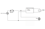
I have a question regarding a light fixture I'm building that also has a motor in it. It has geometric shapes that spin slowly around the light (almost like a mobile) and this is what I'm using the motor for. The light fixture will be attached to the ceiling like any normal light fixture or chandelier and I want to use a light switch on the wall to be able to turn it on and off. The light bulbs will be powered by 110V AC. The 12V Synchronous DC motor will be powered by 12V DC. I am using an Inverter which is 12 Volt DC To 110 Volt AC which will be able to accommodate turning both the motor and bulbs on with a flick of the light switch on the wall.

The question I have is in regards to a dimmer switch. I want to use a dimmer switch to be able to make the lights brighter or dimmer. However, because the motor is also being controlled by the dimmer switch I want to know if this will be a problem and what will happen. Will it slow down the rotation? Will It damage the motor? If it will pose a problem are there any simple solutions or work arounds? I haven't purchased the dimmer switch yet. Is there a certain type that will work with this or a certain type that won't?

Just to clarify why I'm going about it this way. Initially I was just going to use an AC 110 V motor so it would all be on AC. The problem was getting UL approval because of the motor. Because I'm using a 12 V DC motor instead it is kind of a loophole for me so I can get UL approval without all the headaches. Using a 12V DC motor will not be a safety concern in terms of UL certification.

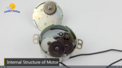
The motor I'm using is a 12V Synchronous DC geared 1 RPM motor. It's just a simple one you can buy on Amazon and I'll post the link to it: https://www.amazon.ca/gp/product/B07YFJR62T/ref=pp...

Also, on a side note I'm not sure what inverter I should use for this project. The choice is between a constant current inverter/driver vs constant voltage inverter/driver. I'm not sure which one to use here.

Any insights would be greatly appreciated. Thanks!
 

Bluejets

Oct 5, 2014
7,374
Joined
Oct 5, 2014
Messages
7,374
The 12V Synchronous DC motor will be powered by 12V DC
No such mother........ synchronous motors are AC.
Named as such as they run at synchronous speed which is a component of the AC waveform.
 

Harald Kapp

Moderator
Moderator
Nov 17, 2011
14,270
Joined
Nov 17, 2011
Messages
14,270
The light bulbs will be powered by 110V AC. The 12V Synchronous DC motor will be powered by 12V DC. I am using an Inverter which is 12 Volt DC To 110 Volt AC which will be able to accommodate turning both the motor and bulbs on with a flick of the light switch on the wall.
Absolutely unclear: do you really mean to generate the 110 V (AC) from 12 V (DC)? That's what an inverter does.
If so: Where's the switch located? On the 110 V side or on the 12 V side?
Or do you mean when you state "inverter" a 12 V (DC) power supply powered by 110 V mains?

The motor I'm using is a 12V Synchronous DC geared 1 RPM motor.
It is not. Or is it? The seller seems to be clueless himself. Look at the type label:
1724302233017.png

It states 12 V DC and then it states 50/60 Hz. A contradictio in adiecto."

Using a 12V DC motor will not be a safety concern in terms of UL certification.
Maybe not the motor, but the 12 V source powered by 110 V mains.

The choice is between a constant current inverter/driver vs constant voltage inverter/driver.
That is not a choice for a motor. Motors are typically powered by voltage sources. Current adjusts automatically acc. to the power requirements.

The question I have is in regards to a dimmer switch. I want to use a dimmer switch to be able to make the lights brighter or dimmer. However, because the motor is also being controlled by the dimmer switch I want to know if this will be a problem and what will happen. Will it slow down the rotation? Will It damage the motor?
The answers strongly depend on clarification of the above issues. A true synchronous motor's rotational speed is little affected by variations in voltage. The rotational speed depends mainly on the frequency of the power supply (aka mains?). Of course, when the voltage is too low, the motor will slip and speed will go down.
Using a dimmer with an electric motor is not a good idea. It can cause a number of undesirable effects.


From my perspective a working setup could like like this:
  • 110 V AC power (dimmed) to the light bulb(s).
  • 12 V DC power (not dimmed) to the motor.
  • 110 V AC to 12 V DC power supply to provide power for the motor
  • mains switch on the 110 V AC primary side
1724303506142.png
 

cb33

Aug 21, 2024
8
Joined
Aug 21, 2024
Messages
8
Thanks very much for your responses. They are very informative. The diagram all looks correct in terms of what I've been trying to explain. However, this issue is the main switch is the dimmer. I looked into the motor a bit more and it's not a Synchronous motor. It's just a geared motor. I'll attach a pic of the inside.
 

Attachments

  • Screenshot (220).png
    Screenshot (220).png
    721.7 KB · Views: 2

cb33

Aug 21, 2024
8
Joined
Aug 21, 2024
Messages
8
Absolutely unclear: do you really mean to generate the 110 V (AC) from 12 V (DC)? That's what an inverter does.
If so: Where's the switch located? On the 110 V side or on the 12 V side?
Or do you mean when you state "inverter" a 12 V (DC) power supply powered by 110 V mains?


It is not. Or is it? The seller seems to be clueless himself. Look at the type label:
View attachment 64474

It states 12 V DC and then it states 50/60 Hz. A contradictio in adiecto."


Maybe not the motor, but the 12 V source powered by 110 V mains.


That is not a choice for a motor. Motors are typically powered by voltage sources. Current adjusts automatically acc. to the power requirements.


The answers strongly depend on clarification of the above issues. A true synchronous motor's rotational speed is little affected by variations in voltage. The rotational speed depends mainly on the frequency of the power supply (aka mains?). Of course, when the voltage is too low, the motor will slip and speed will go down.
Using a dimmer with an electric motor is not a good idea. It can cause a number of undesirable effects.


From my perspective a working setup could like like this:
  • 110 V AC power (dimmed) to the light bulb(s).
  • 12 V DC power (not dimmed) to the motor.
  • 110 V AC to 12 V DC power supply to provide power for the motor
  • mains switch on the 110 V AC primary side
View attachment 64476
 

Attachments

  • Moto-Dimmer-Converter.png
    Moto-Dimmer-Converter.png
    13.1 KB · Views: 6

cb33

Aug 21, 2024
8
Joined
Aug 21, 2024
Messages
8
Thanks again for taking the time to look this over. I attached an updated sketch of your original drawing with a few modifications. One of the main issues here is it's in a house and the main switch for the light is the dimmer. Also, it's not a true Synchronous motor.
 

Harald Kapp

Moderator
Moderator
Nov 17, 2011
14,270
Joined
Nov 17, 2011
Messages
14,270
I attached an updated sketch of your original drawing
The power suppy (110 V / 12 V) may not be happy with the input from a dimmer controlled mains.
I think you'll have to live with dimmer+switch as shown in my diagram.
 

Bluejets

Oct 5, 2014
7,374
Joined
Oct 5, 2014
Messages
7,374
Actually it's not a synchronous motor even though the company says it is. It is a DC gear motor.
Well, the word synchronous and the frequency 50/60hz say it is which is 2:1 against the 12v DC.
I've seen worse with stuff from PRC.
Every image I could find in relation to 12v synchronous motor TYC-50 say it is AC.

I'd tend to go and find a "real" synchronous motor @110v mains rating and use that.
Problem is when you start adding a dimmer as these motors run at 50/60 cycles per second and a dimmer of any kind may chop the frequency to the point where your speed is no longer constant (if that bothers you)
 

Delta Prime

Jul 29, 2020
2,987
Joined
Jul 29, 2020
Messages
2,987
I attached an updated sketch of your original drawing with a few modifications. One of the main issues here is it's in a house and the main switch for the light is the dimmer.
Replace the schematic SPST switch
Symbol with block diagram of a dimmer; to avoid confusion. But your passed , that now...best advice was previously mentioned.
 

73's de Edd

Aug 21, 2015
3,730
Joined
Aug 21, 2015
Messages
3,730
Cee Bee Tho'ity twee . . .

Here is the way I am seeing it . . . . with your previously supplied option, shown below, being the best choice . . . . . BUT, with its shortcoming . . . . which is solvable.

1724485088207.png

This is just fine with the dimmer setting being at normal maximum output.
As you start decreasing the voltage to the lamp, all is well, but at the motor, that DC voltage will decrease from that specified 12VDC.
That DC motor will progressively slow down and at lower dimming than half, its going to be noticeable from that initial 1 RPM.
If the AC voltage out from the dimmer is decreased to even 1/3 more . . . . is that motor even going to run ? . . . . but definitely . . .at a MUCH slower speed.
Wouldn't you ideally, like to have that motor speed rock stable from a max brite lamp level on down to 1/3 brightness lamp level?
The way I see to do that is to use an old school wall wart inductive transformer of 120VAC in and 12VAC output and that 12VAC output is run into a voltage tripler circuit using 470ufd filter capacitor sets and then fed into a normal LM7812 linear voltage regulator and lightly filtered at its
output and then feed its stable and regulated 12VDC @` 330 ma pull, to the motor.
In this manner, normal motor speed will be maintained down to 1/3 lamp brightness and motor speed, THEN only decreases below that set dimmer threshold.

If being of interest . . . . . I will poke up a schematic of same . . . if so later requested.

will not be a safety concern in terms of UL certification.
If this is to be manufactured . . . . .best disregard its utilization.

73's de Edd . . . . .

When I was just a kid, my big sister thought that she was s o o o o o smartie pants . . . . she said onions are the only food that makes you cry,

. . . . . so I threw a coconut at her. . . . . . . . cry baby !

.
 
Last edited:

cb33

Aug 21, 2024
8
Joined
Aug 21, 2024
Messages
8
wall wart inductive transformer
That sounds very interesting
Cee Bee Tho'ity twee . . .

Here is the way I am seeing it . . . . with your previously supplied option, shown below, being the best choice . . . . . BUT, with its shortcoming . . . . which is solvable.

View attachment 64482

This is just fine with the dimmer setting being at normal maximum output.
As you start decreasing the voltage to the lamp, all is well, but at the motor, that DC voltage will decrease from that specified 12VDC.
That DC motor will progressively slow down and at lower dimming than half, its going to be noticeable from that initial 1 RPM.
If the AC voltage out from the dimmer is decreased to even 1/3 more . . . . is that motor even going to run ? . . . . but definitely . . .at a MUCH slower speed.
Wouldn't you ideally, like to have that motor speed rock stable from a max brite lamp level on down to 1/3 brightness lamp level?
The way I see to do that is to use an old school wall wart inductive transformer of 120VAC in and 12VAC output and that 12VAC output is run into a voltage tripler circuit using 470ufd filter capacitor sets and then fed into a normal LM7812 linear voltage regulator and lightly filtered at its
output and then feed its stable and regulated 12VDC @` 330 ma pull, to the motor.
In this manner, normal motor speed will be maintained down to 1/3 lamp brightness and motor speed, THEN only decreases below that set dimmer threshold.

If being of interest . . . . . I will poke up a schematic of same . . . if so later requested.

will not be a safety concern in terms of UL certification.
If this is to be manufactured . . . . .best disregard its utilization.

73's de Edd . . . . .

When I was just a kid, my big sister thought that she was s o o o o o smartie pants . . . . she said onions are the only food that makes you cry,

. . . . . so I threw a coconut at her. . . . . . . . cry baby !

.
This definitely sounds of interest. That's a very unique approach to this. I do need to be able to get parts that are UL certified and I also will need to get this setup UL approved once it is done. This does look like it has great potential. Great idea!
 

Delta Prime

Jul 29, 2020
2,987
Joined
Jul 29, 2020
Messages
2,987
This does look like it has great potential. Great idea!
I would consider.
(I approved this AI generated response) :
Electromagnetic compatibility (EMC) certification is a process that verifies that a product can function in its electromagnetic environment without causing or being affected by electromagnetic interference. EMC certification is required to sell products in the United State.
 

cb33

Aug 21, 2024
8
Joined
Aug 21, 2024
Messages
8
Cee Bee Tho'ity twee . . .

Here is the way I am seeing it . . . . with your previously supplied option, shown below, being the best choice . . . . . BUT, with its shortcoming . . . . which is solvable.

View attachment 64482

This is just fine with the dimmer setting being at normal maximum output.
As you start decreasing the voltage to the lamp, all is well, but at the motor, that DC voltage will decrease from that specified 12VDC.
That DC motor will progressively slow down and at lower dimming than half, its going to be noticeable from that initial 1 RPM.
If the AC voltage out from the dimmer is decreased to even 1/3 more . . . . is that motor even going to run ? . . . . but definitely . . .at a MUCH slower speed.
Wouldn't you ideally, like to have that motor speed rock stable from a max brite lamp level on down to 1/3 brightness lamp level?
The way I see to do that is to use an old school wall wart inductive transformer of 120VAC in and 12VAC output and that 12VAC output is run into a voltage tripler circuit using 470ufd filter capacitor sets and then fed into a normal LM7812 linear voltage regulator and lightly filtered at its
output and then feed its stable and regulated 12VDC @` 330 ma pull, to the motor.
In this manner, normal motor speed will be maintained down to 1/3 lamp brightness and motor speed, THEN only decreases below that set dimmer threshold.

If being of interest . . . . . I will poke up a schematic of same . . . if so later requested.

will not be a safety concern in terms of UL certification.
If this is to be manufactured . . . . .best disregard its utilization.

73's de Edd . . . . .

When I was just a kid, my big sister thought that she was s o o o o o smartie pants . . . . she said onions are the only food that makes you cry,

. . . . . so I threw a coconut at her. . . . . . . . cry baby !

.
If you could help with this a bit more I would really appreciate it. I like your idea but not sure how to execute it.
 
Top