Hi to all,
I'm the OP, returning after a HUGE period of time... So sorry!
I see that, meanwhile, other users have finished the board and got a functioning inverter, while someone else encountered some issues, thus I'm here just to add my last observations / hints that should, hopefully,
clear any remaining doubt, and allow to build a working inverter, since the configuration I'm going to describe worked flawlessy and successfully for me, having by now built three of them.
I'm going to possibly repeat what has already been noted, but for the benefit of those with lesser experience, I'll try to be as comprehensive as possible, so bear with me.
")
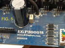
THE COMPONENTS I'VE USED: (namings refer to those of the 'official' schematic EGS031 + EGP3000W by
www.EGmicro.com DWG no. 2013-07-02, you can find the PDF at my post #30 above.
Note: The dimensioning of some components refers to a
500W inverter, since this was the power I needed for my purposes. We'll discuss later on which max. power can be obtained with this project.
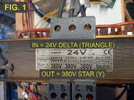
POWER TRANSFORMER:
- 1 pcs. 500 W, three-phase transformer, primary 24 V
DELTA (TRIANGLE) configuration, secondary 380 V
STAR (Y) configuration. (See FIG. 1)
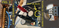
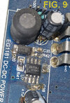
48V DC INPUT SOURCE (CON1 + and CON2 - input connectors) (See FIG. 2)
- Since my max. power operating requirement was of 500W, I've opted for a switching power supply 220-230Vac to 48Vdc 500W 10.4A
Using different sources, care must be taken of not exceeding the 48Vdc limit, I haven't tested above and wouldn't recommend unless thoroughfully checking the affected components for sufficient voltage dimensioning.
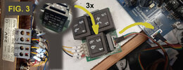
LO-PWR FEEDBACK TRANSFORMERS: (See FIG. 3)
- 3 pcs. single-phase transformers, primary 220-230 V, secondary 12 V, power is not critical, the smaller available, 2 VA is enough. (T1,T2,T3 on schematic) Take care of ensuring the
SAME PHASE on coils when wiring them to CON4 connector, referring to the small black dot on coil diagram. So, when connecting the 12V secondary of the three transformers to CON4, on pin 6,4,2 you'll have the "dotted end" of the transformer, and on 5,3,1 the other.
Using the same reasoning, connect the 220-230V primary of same transformers to the main transformer outputs (a,b,c,n), with "dotted end" to a, b, c
in that order, and the other ends connected together to n.
Remember also the 0.47uF 400V capacitors across a,b,c and n and, an important note, make sure that the counter-intuitive writing "220V - 12V" under the T1-T3 transformers did not mislead you since, visually, one might be led to believe that the rightmost winding is the 12V one and the leftmost the 220V one.
Don't fall for it !!! The 220 side
MUST GO to the power transformer, and the 12V side to CON4 !!!
POWER MOSFETs
- While the schematic would suggest the IRF840, I've observed a considerably lower heating of the heatsink using the 75NF75 featuring a RDS(on) < 0.011 ohm, compared to 0,85 ohm (!) of the IRF840. And although RDS(on) isn't everything in a mosfet, containing power dissipation is a good practice for starting anyway, then we could elaborate further on other models / parameters, depending also on the max. power we intend to squeeze from this application.
VOLTAGE CONTROLLER EG1181:
- I couldn't find that model on the market, but I was able to find the EG1182 that proved compatible and correctly working.
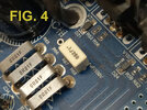
SHUNT RESISTORS 10 mOHM R65 thru R68: (See FIG: 4)
- must be open-air, current sense 1% 1W resistors, like Mouser OAR1R010FLF or similar, length about 12mm.
ASSEMBLY NOTES:
- Insulating, thermal-conductive pads are required between mosfet lugs and heat sink, together with insulating bushing for the fixing screw. In case, add thermal paste and after mosfet / heatsink assembly verifiy effective insulation with ohmmeter.
High current wirings: provide sufficient wire gauge to withstand the currents that are into play, for EGP3000W board 48V input +- I've used 4mmq (square mm) stranded wire.
Make sure also that R29 is 0 ohm (pads shorted) and R34 is not mounted (pads free) Other schematics around are indicating different values for these two, causing confusion and malfunctions.
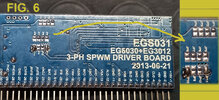
- EGS031 board jumper setup: (See FIG. 6)
JP10 and JP11 closed (short), the remaining all open.
This means:
Functioning mode "01" (JP11 close, JP12 open) = 3-phase open-circuit independent, internally controlled regulation mode.
Soft-start mode (JP10 closed) disabled, when JP10 is open output increases linearly over 3 seconds upon restart.
Output frequency: (default) JP2 open: 50Hz, JP2 closed: 60Hz (JP1 must be always OPEN)
Other jumpers are for special settings, will cover them later, if needed
That's all for now, let me know if something is still unclear, I will try to help if I can.
Roberto