7447 BCD + two 7-segments

NikitaB

Jul 28, 2011
7
Joined
Jul 28, 2011
Messages
7
Hi all,

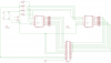
I'm trying to control two common anode 7-segment displays using daisy chained 7447 BCDs, but with no luck. Unlike the 4511 BCD (for common cathodes) the 7447 has no memory latch, and so I'm confused as to how data can be directed from one BCD/segment to another BCD/segment. My setup does work with one 7-segment though :)

This site (http://www.davidswinscoe.com/electronics/components/7447/index.html) says to connect RBO on one to RBI on the second, but no luck there either.

For reference, my circuit is wired up just as detailed here (http://thelearningpit.com/lp/doc/7seg/7seg.html, under the 'Mutiplexed digits' heading) with the 4511 replaced by the 7447 and LE separate from LT and BI. On the 7447, LE is replaced by RBI.

7447 datasheet: http://media.digikey.com/pdf/Data Sheets/Fairchild PDFs/DM7446A, DM7447A.pdf

Schematics, descriptions, and any other forms of help are greatly appreciated - thanks!!!
 

(*steve*)

¡sǝpodᴉʇuɐ ǝɥʇ ɹɐǝɥd
Moderator
Jan 21, 2010
25,510
Joined
Jan 21, 2010
Messages
25,510
Can you show me your schematic and what you mean by "daisy chaining"

Are you trying to multiplex the 2 digits?
 

NikitaB

Jul 28, 2011
7
Joined
Jul 28, 2011
Messages
7
Yes, by daisy chaining I mean multiplexing - sorry for the vocab. confusion. With the 4511 BCD I only had to use 6 pins (using a LabJack with no access to D0-15) and as I only have access to those 6, whatever the setup with the 7447 is, it also needs to use only four pins… I have looked into putting a latch circuit (such as the MC14043B), but that just complicates things and requires more pins.

Attached is the schematic and you'll notice that RBO/BI, RBI, and LT are all tied to +5v. In this setup (with only one 7447) everything works fine. But since there is no latch, connecting two together seems less trivial. In fact, using this schematic, when connecting two 7447's like this, the 7-segments turn off and flicker randomly. I have tried this (from the site mentioned above):

"To use with more than one display connect (Ripple Blanking Output) from most significant 74xx47 to the of the next 74xx47. Connect of the least significant 74xx47 to 5v unless you want the diplay to turn off when the number is 0."

But came up with the same flickering result.

One last note: the schematic doesn't include any actual 7-segments, but instead brings all 7-segment pins out to a DB25. I am planning to run a cable from this board to the 7-segments, connected on another board.

If all else fails, I can place an order for two MC14543b's, which are latch enabled, but it'd be great to figure this situation out.

Thanks for the help!
 

Attachments

  • schem.png
    schem.png
    60.9 KB · Views: 8,154

(*steve*)

¡sǝpodᴉʇuɐ ǝɥʇ ɹɐǝɥd
Moderator
Jan 21, 2010
25,510
Joined
Jan 21, 2010
Messages
25,510
Ah!

You misunderstand multiplexing. You only need one 7447 and you connect all (both) of the displays in parallel. Then you switch the common (anode or cathode) of the displays so that only one display is enabled at a time. You do this very fast so that nobody sees them flashing.
 

davenn

Moderator
Sep 5, 2009
14,470
Joined
Sep 5, 2009
Messages
14,470
Ah!

You misunderstand multiplexing. You only need one 7447 and you connect all (both) of the displays in parallel. Then you switch the common (anode or cathode) of the displays so that only one display is enabled at a time. You do this very fast so that nobody sees them flashing.

thanks steve
you also refreshed my memory :)
Thats what I was desparately trying to remember. Its been years since I used the 7447 to drive displays. maybe now my google searching will reveal some circuits as it will for NikitaB. The searches I did last week didnt get me anywhere haha

Dave

PS congrats on clearing 7000 posts woohoo!!
 

davenn

Moderator
Sep 5, 2009
14,470
Joined
Sep 5, 2009
Messages
14,470
gosh its difficult to find specific info out there for driving multiple displays from a 7447

but here's one appln note that may help....


cheers
Dave
 

NikitaB

Jul 28, 2011
7
Joined
Jul 28, 2011
Messages
7
Thank you for the all of the advice!

The idea behind multiplexing now makes much more sense, but I am unsure as to the ability of my system to cycle the anodes fast enough to create the impression of a static display. LabJack switching takes on the order of 0.02 seconds, and with two displays, writing, turning on, turning off, writing new, turning on, turning off may cause noticeable issues. If only the system were based off of a BasicStamp or Arduino...
 
Top