74LS161 driven by MX045HS

jmarco

May 1, 2023
4
Joined
May 1, 2023
Messages
4
Hello,

I am working on a Ben Eater-inspired VGA project, except his project uses a 10MHz crystal to fake a 800x600 resolution signal, but I'm using a 25.175MHz crystal to create a proper 640x480 resolution signal.

In testing, I used an Arduino to generate a slow clock pulse so I could confirm that my horizontal and vertical signals were being properly generated at the time steps dictated by the VGA standard. I rigged LEDs up to my counters and verified that the HSYNC/HBLANK/VSYNC/VBLANK signals changed state at the correct time steps.

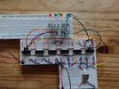
When I disconnected the Arduino and connected my crystal - a MX045HS - it didn't seem to work correctly. The LEDs didn't change state at all. By the conclusion of my troubleshooting efforts, I simply daisy-chained two 74LS161 (digital counter) chips and connected them to the crystal, but with LEDs connected to the outputs of the counter, I verified that it wasn't changing state - some LEDs stayed on, some stayed off. I connected an LED to the output of the crystal and confirmed that it lit with half brightness, consistent with the LED flashing off and on at very high speeds.

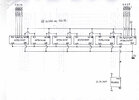
So right now, I just have the MHX045HS crystal, two 74LS161 counters (with the carry-out of one connected to the "increment" pin of the other), and an indicator LED - the rest of my VGA circuit is not connected. As far as I can tell, the counter is not changing state. I don't have access to an oscilloscope. The "increment" pin of the low-order 74LS161 is connected to 5V, and the crystal is connected to CLK.

If anyone has an insights, or further troubleshooting suggestions, they would be greatly appreciated. Thank you in advance!

John
 
Last edited by a moderator:

davenn

Moderator
Sep 5, 2009
14,470
Joined
Sep 5, 2009
Messages
14,470
If anyone has an insights, or further troubleshooting suggestions, they would be greatly appreciated. Thank you in advance!

John

hey John,
Welcome
how about some circuits/schematics of what you are trying to achieve would help people trying to help you :)
 
Last edited:

danadak

Feb 19, 2021
1,064
Joined
Feb 19, 2021
Messages
1,064
What is frequency out of the MX045HS ?

What other signals does the Arduino apply to the 74LS161 ? Besides clock ?


Regards, Dana.
 

kellys_eye

Jun 25, 2010
6,512
Joined
Jun 25, 2010
Messages
6,512
The LS161 is a presettable counter. What state are the preset pins?
 

jmarco

May 1, 2023
4
Joined
May 1, 2023
Messages
4
Hello,

Thank you for your replies. I've rigged up a test circuit to illustrate the problem, and I'm attempting to attach the images to this reply. Please forgive my artwork in the schematic, I don't yet know how to use those fancy schematic authoring tools. In the schematic, I omitted several of the irrelevant connections (like power and ground) for clarity.

In my test circuit, I have six 4-bit counters connected such that the carry-out of one triggers the increment of the next. As such, the high-order (leftmost) counter should wrap at 16,777,216/25,175,000 seconds, which should be readily discernible to the human eye. I've connected LEDs to the lowest-order and highest-order bits to see any activity. However, when I connect the output of the crystal to the CLK of the counters, nothing increments. I confirmed this by checking several of the intervening bits, none of them are observably changing state. I also tried checking the crystal output and confirmed that the LED illuminates at approximately half-brightness, consistent with a square wave at 50% duty cycle.

In contrast, I also wrote a small Arduino script that does PWM output with 50% duty cycle on pin 5 (this should generate a relatively high-frequency square wave). I unplugged the crystal output and connected Arduino pin 5 to the counters' CLK. In this case, the counters incremented correctly.

@danadak: the frequency is 25.175MHZ. In the test circuit, the only input from the Arduino is the power pins (it's providing 5V and GND), except when I disconnect the output from the crystal - then I use PWM on pin 5 to provide a high frequency square wave (though not as high as the crystal, I think it's like 500khz or so).

@kells_eye: I am not presetting the counter, I have the _LOAD_ pin (negative pulse) hard-wired to 5V. As such it has a random value when it powers on. With the crystal connected this value doesn't change; with the Arduino connected, it increments predictably. Interestingly, the counters initialize to 0 when Arduino is connected, but initialize to random values when connected to the crystal.

Thank you all again for your assistance.

John
 

Attachments

  • circuit_schematic.jpg
    circuit_schematic.jpg
    182.5 KB · Views: 5
  • circuit_photo.jpg
    circuit_photo.jpg
    332.6 KB · Views: 5

kellys_eye

Jun 25, 2010
6,512
Joined
Jun 25, 2010
Messages
6,512
Don't see the power/ground connections on your images (for the clock module). Is the ground common to all boards?

Those prototype boards are also prone to loose connections causing all sorts of issues.
 

jmarco

May 1, 2023
4
Joined
May 1, 2023
Messages
4
Thank you @kellys_eye, the power and ground are connected on all the breadboards. I double-checked that there is connectivity between the crystal output and the the clock inputs of the counters. I expect that the connectivity is sufficient as it behaves properly with the Arduino pin providing the clock pulse. However, after reading your post I searched around and some sites are indicating that 25mhz might be too fast for a breadboard circuit - is this definitely the case? Is this remedied by connecting it to a PCB?
 

danadak

Feb 19, 2021
1,064
Joined
Feb 19, 2021
Messages
1,064
What is actual goal, just to generate a low freq clock ? If so what is the freq of the clock you
are trying to get ?

If interested I can show you info on a programmable part, no code needs to be written,
that can do this all on one chip. Including routing internal between cntrs and out to pins.
And including a HF clock.

The 25 Mhz clock, is that just to get a specific LF clock ?


Regards, Dana.
 

jmarco

May 1, 2023
4
Joined
May 1, 2023
Messages
4
The 25mhz clock is for the sake of creating a proper 640x480 VGA signal, which requires 25mhz clock. The purpose of the circuit with the counters is to troubleshoot the behavior of the 25mhz clock, which doesn't seem to be properly driving the counter chips.
 

danadak

Feb 19, 2021
1,064
Joined
Feb 19, 2021
Messages
1,064
Another way of doing this :


Regards, Dana.
 

kellys_eye

Jun 25, 2010
6,512
Joined
Jun 25, 2010
Messages
6,512
some sites are indicating that 25mhz might be too fast for a breadboard circuit
Way past anything I'd try - 10MHz would be my limit but perhaps psuhing it to 20MHz with careful wiring (i.e. short, direct) If you plan to take your project further then a 'scope and/or analyser is a must. i.e. using a 'scope would find the issue in minutes......
 
Top