Advice needed on auto switch design

Bongodrummer

Sep 6, 2010
8
Joined
Sep 6, 2010
Messages
8
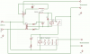
Hi Guys, I am quite new at this stuff and would really appreciate any views people might have on this design I have been thinking about for an auto switch.
The auto switch itself is used to aromatically turn on my dust extractor when I use any hand power tools plugged into the auto switch.

I know that most of these use power transformers but I wondered if one that uses a reed switch, activated by a coil which is magnetised when the power tool is turned on might also work? Does this seem workable (drawing attached)?
attachment.php


Thanks,
Bongo
www.floweringelbow.co.uk
 

Attachments

  • dust auto switch.png
    dust auto switch.png
    68.3 KB · Views: 2,854

Resqueline

Jul 31, 2009
2,848
Joined
Jul 31, 2009
Messages
2,848
Yes, that seems to me like it'll work. You just have to use a thick enough magnet wire to carry the max current, with enough turns to switch it on with minimum current.
A heatsink for the rectifier may be neccessary.
 

Bongodrummer

Sep 6, 2010
8
Joined
Sep 6, 2010
Messages
8
Hi, thanks for the reply.
I must admit I posted this on another forum as well :eek:, and there I was told that it would not work with the bridge rectifier in there. I don't really understand why not though. Like you say, as long as the coil was decent sized wire with low resistance... I guess there would be a small voltage drop, and slightly less power going to the tool - but that would probably be negligible - if it would work...

I put it in there because I guessed that the reed switch would be flicking about on and off a lot with a simple coil in the AC live wire.

Reckon a 25A bridge with a small heat sink would suffice?

Bongo
www.floweringelbow.co.uk
 

Militoy

Aug 24, 2010
180
Joined
Aug 24, 2010
Messages
180
Draw out the diodes in the bridge rectifier - follow the current from the source to the power tool - and it will become more clear why the person on the other site said it won't work. On each half cycle, current is blocked by the opposing side of the bridge. The power tool will never get power.
 

Resqueline

Jul 31, 2009
2,848
Joined
Jul 31, 2009
Messages
2,848
Calculate the heatsink from roughly 2V drop over the bridge, giving you a loss of 20W with a 10A tool current.
Yes, I'd also reckon the reed would easily buzz w/o the rectifier (& the cap helps too).
Of course one could imagine also putting a fuse in there, corresponding with the magnet wire size to prevent the coil from burning out.
Militoy; with the tool being in series with the bridge AC terminals, and its +/- out being shorted by the low-resistance coil, I can't see why the tool won't get any power..
After all we're talking about a small low-turn 18-gage (or thereabouts) wire coil here.
 

Militoy

Aug 24, 2010
180
Joined
Aug 24, 2010
Messages
180
Calculate the heatsink from roughly 2V drop over the bridge, giving you a loss of 20W with a 10A tool current.....
Militoy; with the tool being in series with the bridge AC terminals, and its +/- out being shorted by the low-resistance coil, I can't see why the tool won't get any power..
After all we're talking about a small low-turn 18-gage (or thereabouts) wire coil here.

You've pointed out the problem yourself, above. Most reed relay coils have a resistance that can't really be catagorized as low - usually on the order of at least tens of ohms for low-voltage coils - sometimes hundreds. Because of the diode orientation, the whole of the 10A tool current must pass through the coil. If we consider power loss in a fairly low resistance coil (let's say only 10 ohms) - 10A squared through the 10 ohms will result in 1000W loss in the coil - you begin to see a possible problem getting power to the tool. Theoretically - it might be possible to find a very low voltage relay with a low resistance coil - but who would buy a 3V relay that draws a nominal 5 or 10A to energize the coil?

I suppose it might be possible to wind a coil and wrap it around a magnetic reed switch - and get enough flux to trip the switch reliably. It does sound like a bit of a science project though - since the coil flux will be dependant on the current drawn by the tool. I suspect if a working solution is found - the wire size in the coil will be something larger than 18 gauge. Might make an interesting experiment though.
 
Last edited:

Bongodrummer

Sep 6, 2010
8
Joined
Sep 6, 2010
Messages
8
Calculate the heatsink from roughly 2V drop over the bridge, giving you a loss of 20W with a 10A tool current.
Yes, I'd also reckon the reed would easily buzz w/o the rectifier (& the cap helps too).
Of course one could imagine also putting a fuse in there, corresponding with the magnet wire size to prevent the coil from burning out.
Militoy; with the tool being in series with the bridge AC terminals, and its +/- out being shorted by the low-resistance coil, I can't see why the tool won't get any power..
After all we're talking about a small low-turn 18-gage (or thereabouts) wire coil here.

Ahhh, some reassurance :D I had been scratching my head, drawing it out and trying to work out why it wouldn't work for ages...

I think I will have to go ahead and try it, with some caution, of course :p

Question: loosing 20W all the time is small fry, compared to the 1200W extractor, but... If I added another bridge in parallel, could I reduce the losses and run cooler/more reliably?? As I have a bunch of them anyway, it would be no problem to stick another in there if it was worth it.
 

Bongodrummer

Sep 6, 2010
8
Joined
Sep 6, 2010
Messages
8
Theoretically - it might be possible to find a very low voltage relay with a low resistance coil - but who would buy a 3V relay that draws a nominal 5 or 10A to energize the coil?

I was thinking I could make the coil myself as it wll be a low number of turns and just somehow glue a reed switch in place so that it is activated.. Might that work?
 

Militoy

Aug 24, 2010
180
Joined
Aug 24, 2010
Messages
180
Seems like it might work - as I posted above (maybe we cross-posted), the flux in the coil will be set up by the current drawn by the tool. So your tests should include both the lightest load and heaviest that you anticipate. Once you get a coil working under both conditions, as a safety precaution either measure resistance and calculate power loss, or measure temperature rise at full load. Size your coil wire accordingly. The reed relays I use for HV switching are made by Kilovac. The glass body of the reed switch is held in place in the coil bobbin using only an end piece of a nylon tie wrap as a wedge. Sometimes, I'll add a dab of silicone RTV for insurance.
 
Last edited:

Bongodrummer

Sep 6, 2010
8
Joined
Sep 6, 2010
Messages
8
Yep, cross posting did occur :eek:
Thanks for the advice. Any specifics on how to orient the reed switch? Sounds like you actually put it inside the coil? I was expecting to position it somewhere on the outside. I guess I can just play about and fin a position where it is nicely closed?
 

(*steve*)

¡sǝpodᴉʇuɐ ǝɥʇ ɹɐǝɥd
Moderator
Jan 21, 2010
25,510
Joined
Jan 21, 2010
Messages
25,510
The other option is one of those power boards that turn on other slave outlets when load is drawn from a master outlet.

The problem with them is that the maximum load on the master outlet is often limited.

edit, of course you could put a few diodes in series (and anti-parallel) and use the voltage drop to trigger an optocoupler and then either a solid state relay, or a triac, etc, to switch the axillary load (the extractor fan).
 
Last edited:

Militoy

Aug 24, 2010
180
Joined
Aug 24, 2010
Messages
180
There are certainly several ways to solve the design problem. I use optoisolators and optoMOS switches in some of our products - but I have to be somewhat cautious in my use of them - as most of the stuff I work with has to run at fairly high temperature - and high ambient temperatures tend to mask the picojoule infrared signals that make them work. As far as location of the reed switch - the "normal" fashion is a long, skinny coil, with the switch in the center. Highest flux will be through the center axis of the coil.
 

Resqueline

Jul 31, 2009
2,848
Joined
Jul 31, 2009
Messages
2,848
I don't see much benefit to be had here from parallelling bridges. The total loss will only drop by maybe 10% or thereabouts.
The challenge in designing the coil is determined by the current range you need. The final resistance needs of course to be far less than 1 ohm, for stated reasons.
Wind it as Militoy suggest, the coil being as long as the glass body, and as close/tight around it as possible.
Reed sensitivity is "classed" in AT (AmpereTurns) which means that you can wind a (10-turn) test coil to see which ones are most sensitive (if you have several to choose from).
Typical sensitivity is between 30 & 50 AT. From there it's just a matter of calculating the final number of turns, adding some extra turns due to the change in coil form factor.
Of course there are completely different ways to reach the goal, like steve suggests.
 

Bongodrummer

Sep 6, 2010
8
Joined
Sep 6, 2010
Messages
8
Steve - yep, I guess you mean something like this: http://www.freepatentsonline.com/5099157.pdf. I had been considering it, but just wanted something that would turn on the vacuum extractor to full, regardless of any pwm speed control the tool might be doing.

Militoy, Resqueline - Thanks a lot for this, I will try winding it as you suggest and see what we get...
 

Militoy

Aug 24, 2010
180
Joined
Aug 24, 2010
Messages
180
....
Militoy, Resqueline - Thanks a lot for this, I will try winding it as you suggest and see what we get...

If you do get it working, the kudos go to Resqueline - I mainly jumped in as a "naysayer". I still think you may have some difficulty balancing between closing the switch at light loads, and permanently magnetizing the reed at high current, so it's stuck closed. As I noted earlier - it will make an interesting "science project". Good luck!
 

Lenp

Sep 8, 2009
24
Joined
Sep 8, 2009
Messages
24
There are small CT (Current Transformers) that can sense the current drawn on AC. The load sense wire is passed through the center hole of the coil. There are some that will drive an LED directly. Use one of those to turn on an optical isolator that can then either turn on a conventional relay or a SSR (Solid State Relay) to control the power load.
Here's a link to products I've used before http://www.crmagnetics.com/products/Assets/ProductPDFs/cur_I_a.pdf

Len
 

Militoy

Aug 24, 2010
180
Joined
Aug 24, 2010
Messages
180
OK – I’ll have to tip my hat to Resqueline on this one. I didn’t think it would be so simple – but this idea was sticking in my craw – so I tossed together a test mule today during my lunch hour, and it works pretty well. The mag switches I had readily available for the test were Hamlin DRR-129 series – these ones are rated at around 50 Ampere-Turns in sensitivity. In our usage in ATE, they’re usually associated with a Coto 24VDC solenoid coil – a 1300 series.

When designing the coil, I decided on 5W max power loss at 25A as a limit – and estimated a coil length of around 1.25 inches as being about right to stay centered over the sweet spot of the switch, which is 2 inches (max) in length. I picked 16 AWG magnet wire as being about right to meet the coil length to make up 0.008Ω. The coil form I picked off my desk to wind the wire on was a plastic soldering tool – 0.245 in diameter. The length of wire was selected from a wire chart for DC resistance – and the ends stripped and tinned and tested for resistance before winding. The finished coil length is 1.30 inches, and 22 turns total. It could be tightened up a bit with more careful winding – but remember – this was a quick lunch break project. I put two layers of heat shrink over the glass switch – which is 0.207 max in diameter – then slipped the switch into the coil. I connected to an IR 110MT80KB bridge rectifier for the test. This is an 800V 110A bridge – much bigger than needed – but again, I was in a hurry, and I had a box of these in my office. This bridge is also big enough in size that I didn’t need to worry too much about heat sinking during the test.

The test results were surprising. The switch pulls in at 3.0A – or 66 Amp-Turns – and drops out at 1.80A (40 AT). As would be expected with 5W dissipation – the coil gets pretty hot up at 25A current – but the switch works fine there, and doesn’t stick from the high flux, or drop out from the initial temperature rise. I imagine that after awhile up at full power, this particular design would eventually reach the curie temp of the reed elements, and they would fail. But with a little dialing-in of the wire size, and limiting current to keep temperature rise under control – the concept will work.
 

Attachments

  • IMG.jpg
    IMG.jpg
    74 KB · Views: 265

Bongodrummer

Sep 6, 2010
8
Joined
Sep 6, 2010
Messages
8
Cool!

Bit late I know, but haven't checked back in ages. Thanks for giving it a test - I am just getting round to building this, and it is nice to know it actually works. ;)
Thanks for that.
 
Top