View attachment 18740
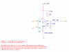
This is the simpler way to do what you want. This is a widely used trick. You only need one regulator, and no analogue switch.
When the voltage select line is low, the MOSFET is OFF and the output voltage is set by R105 and R113. Since the ADP171's reference voltage is 0.5V, the output voltage will be 1.0V.
When the voltage select line is high, the MOSFET is ON, and it connects the new 10 kΩ resistor in parallel with R113. Therefore there is 10 kΩ from the output to the ADJ pin, and 5 kΩ from the ADJ pin to 0V, so the output voltage will be 1.5V.
The enable pin operates as normal.