FredHedgecoth
- Aug 14, 2026
- 5
- Joined
- Aug 14, 2026
- Messages
- 5
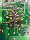
I am doing a (hopefully) minor repair on a Yamaha MX12/4 audio mixer. An NJM4580 is being replaced but some traces are burned and I’m not sure where the jump wires should go. If someone can tell me which endpoints go together I may be able to whoop this puppy. I am also attaching the service manual to assist.
The one I’m baffled by is pin 2 - ? I tried to attach the service manual for this model so anyone that can read it might be able to assist me here but it is too large. The link for it is found at
https://www.manualslib.com/download/4138818/Yamaha-Mx12-4.html.
This section of the circuit board controls the Group 1 & 2 controls between sliders 4 and 5 from right.
Here are the connections as best I can determine them:
pin 1 - node 16
pin 2 - node ?
pin 3 - node 15
pin 4 - node 13 & 14 (?)
pin 5 - node 12
pin 6 - node 11
pin 7 - node 10
pin 8 - node 9
As you can tell, I am a novice with experience limited to simple soldering and continuity testing. If anyone can direct me further with this project it may save a useful piece of equipment from the dump. Many thanks!
The one I’m baffled by is pin 2 - ? I tried to attach the service manual for this model so anyone that can read it might be able to assist me here but it is too large. The link for it is found at
https://www.manualslib.com/download/4138818/Yamaha-Mx12-4.html.
This section of the circuit board controls the Group 1 & 2 controls between sliders 4 and 5 from right.
Here are the connections as best I can determine them:
pin 1 - node 16
pin 2 - node ?
pin 3 - node 15
pin 4 - node 13 & 14 (?)
pin 5 - node 12
pin 6 - node 11
pin 7 - node 10
pin 8 - node 9
As you can tell, I am a novice with experience limited to simple soldering and continuity testing. If anyone can direct me further with this project it may save a useful piece of equipment from the dump. Many thanks!