People,
Have a "module" that controls the opening/closing of 1980's Firebird and Sunbird, Fiero, etc, headlight doors. Similar to this one on ebay, for reference:
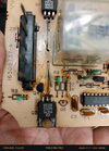
Picture I have included below shows a burnt part, kinda elongated metallic "rod", not sure what to call it, to the right of F2. Any idea what amps that thing could be? Friend of mine is trying to repair it as he has some background in this type of repair, but he is not sure what the thing is (he does not speak english and asked me to poke around to find out). I said the people on this forum have helped me before on such matters.
Any advice appreciated.
Have a "module" that controls the opening/closing of 1980's Firebird and Sunbird, Fiero, etc, headlight doors. Similar to this one on ebay, for reference:
Picture I have included below shows a burnt part, kinda elongated metallic "rod", not sure what to call it, to the right of F2. Any idea what amps that thing could be? Friend of mine is trying to repair it as he has some background in this type of repair, but he is not sure what the thing is (he does not speak english and asked me to poke around to find out). I said the people on this forum have helped me before on such matters.
Any advice appreciated.
")