Carbon Composition Resistor or Inductor?

H2814D

Nov 4, 2017
258
Joined
Nov 4, 2017
Messages
258
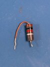
Hi all. This part has me confused. The color code (Brown, Black, Red, Silver) for it to be a resistor, would make it a 1K Ohm value with a 10% tolerance. Testing it with a multimeter set on Ohms, it comes out to 8.3 ohms, which would obviously be quite low for the value, if it is a resistor.

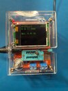
When I insert it into a component checker, it returns as an 8.3 ohm .90 uH inductor (tester uses mH instead of uH, I think- see the pic). The same color code (Brown, Black, Red, Silver) in an inductor chart shows it would be a 1.02 uH inductor with a 10% tolerance, which would almost fit the tolerance. However, if I change the tolerance to 5% (Gold), the app I am using turns it into a 10.2 uH inductor with a plus/minus 5% tolerance. I wouldn't think the change of a tolerance would also change the uH value, would it? Maybe a glitch in the app I'm using?

So I can't tell if it is an inductor or a Carbon Composition Resistor, although the pictures I have looked at so far would indicate the latter. Does the coloring on the long leg of the component indicate something? It has a brown colored coating on it too. I don't think typical two lead inductors are polarized, are they?

So thanks in advance for your replies.
 

Attachments

  • 1K Carbon Composition Resistor or Inductor.jpg
    1K Carbon Composition Resistor or Inductor.jpg
    92.4 KB · Views: 18
  • Component by Itself.jpg
    Component by Itself.jpg
    37.2 KB · Views: 18
  • Component in Tester.jpg
    Component in Tester.jpg
    62.4 KB · Views: 18
Last edited:

Bluejets

Oct 5, 2014
7,374
Joined
Oct 5, 2014
Messages
7,374
I'd go with the component tester.

Physically it looks intact so why would you suspect it as "faulty" in the first place?

Placement in the circuit would be a dead give-away but an inductor at 10%, (silver) sounds about right on the tester.

Testers have tolerance to be taken into account as well remember.
 

H2814D

Nov 4, 2017
258
Joined
Nov 4, 2017
Messages
258
Thanks for your reply, Bluejets. My reason for thinking it is faulty is because after doing my research, I found that a carbon composition resistor apparently has a history of failure, and if I test it as a resistor, it it obviously not giving me the correct value. As an inductor, it is, at least, very close.

So I'm not quite sure how it would be placed in a circuit, since I'm not at that level of electronics know-how. So are there any hints as to what I should look for before and after it that would lead me in the right direction as to what it is for certain. I do not have a schematics diagram for this thing either. It is in a component of a car stereo system called a CDM (Control Data Module) made by Delco. I've worked on it here before, but was not successful. I'm giving it another shot now.
 

Bluejets

Oct 5, 2014
7,374
Joined
Oct 5, 2014
Messages
7,374
My reason for thinking it is faulty is because after doing my research, I found that a carbon composition resistor apparently has a history of failure, and if I test it as a resistor, it it obviously not giving me the correct value. As an inductor, it is, at least, very close.
As before, damaged item (in the instance of a resistor) would be obvious.

I'll take an educated view here and say given your apparent inexperience, trying to track errors in the board in question would be well beyond your capability.

That said, you could post close-up clear images of both sides of the area in question and some degree of errors being experienced, the latter being most important aspect of the whole answer, rather than your so-called diagnosis.

Access to any circuit diagrams would be a big plus.
 

Delta Prime

Jul 29, 2020
2,987
Joined
Jul 29, 2020
Messages
2,987
It is in a component of a car stereo system called a CDM (Control Data Module) made by Delco.
Indeed, difficult in finding a schematic, but with that said…
Would your “car stereo system”include a tape deck along with a five band equalizer?
It would narrow my search for your particular control data module.
 

H2814D

Nov 4, 2017
258
Joined
Nov 4, 2017
Messages
258
Indeed, difficult in finding a schematic, but with that said…
Would your “car stereo system”include a tape deck along with a five band equalizer?
It would narrow my search for your particular control data module.
Thanks Delta. Yes. you are correct. The CDM is part of a three piece system used on 88-94 Chevy trucks. This particular CDM is Model #16169561.

The part of the circuit I am now most interested in is whatever it is that provides the voltage to the IC (I don't know which IC it is) that is responsible for the clock timing and radio station frequencies for the display functions now. It is supposed to be the same one. I have everything else working (left/right/front/rear speaker, volume, fade/balance, AM/FM, on/off, etc.). So this is the last thing now.

From my research, my problem may be a lack of + voltage to the IC that controls the clock and radio stations, which may be as simple as a bad solder joint, or a high resistance resistor in the supply voltage to that IC. My troubleshooting now is just to try and check the components in the circuits I am relatively sure are from the voltage supply circuit to the unknown IC, and there are several of them in there with many pins on each of them. Thus the reason why I am now checking on that component up there that I'm not sure what it is.

If you can help with that schematic, that would be great.
 

H2814D

Nov 4, 2017
258
Joined
Nov 4, 2017
Messages
258
I was able to get this figured out. I've been messing with it for at least two years and have another thread here (quite lengthy) where there are a lot more details, but after following voltage paths from the power chip, I was led to an e-cap that I had already replaced with a quality new one when I first starting working on this thing. There were no continuity issues after replacement, as I always check the paths to ensure my solders were good and to verify polarity before powering anything up. Note that the original issue was an inability to change the clock from its 1:00 position and the frequency wouldn't change from 98.1. Both of these numbers are what the unit powers up to when initially supplying voltage to the unit. Not being able to change them has become a problem for many of these units as they age.

While following the voltage after the cap, it didn't seem right, so I removed it. After removing that cap it checked out fine as far as uF, ESR, and in a component checker. I replaced it anyway. This time, after powering up, all of my display functions worked properly. I was able to change the clock and the radio station frequency on the head unit. I attached a pic of the cap (47uF, 16V) I replaced. So at least I can put this one away now, but thanks, all, for trying to help.
 

Attachments

  • Clock and Frequency Timing Issue.jpg
    Clock and Frequency Timing Issue.jpg
    127.8 KB · Views: 5
Top