Jimitrader
- Oct 28, 2016
- 13
- Joined
- Oct 28, 2016
- Messages
- 13
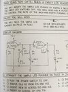
Hello i am experimenting with Cd4001 quad nor gate (fancy LED flasher) from my radio shack digital projects workbook 2.
1. Is it possible to use the other side of the 4001? as i am only using 1-7 and pin 14 for power?
2. why would the leds blink once while turning pot when power is off? is there a way to stop that from happening? I am going to add a ping file showing the design.
1. Is it possible to use the other side of the 4001? as i am only using 1-7 and pin 14 for power?
2. why would the leds blink once while turning pot when power is off? is there a way to stop that from happening? I am going to add a ping file showing the design.