Circuit Analysis Help-Delta to Wye

IanPSwift

Sep 17, 2011
6
Joined
Sep 17, 2011
Messages
6
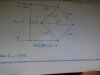
I picked up an essentials of electrical and computer engineering book from the library the other day. It has been fascinating thus far, but I did come to one problem. The book offered this drill exercise, and I couldn't figure out how they solved it. All they want you to do is solve for total ohms. Any help?

Picture of circuit is attached.
 

Attachments

  • studyhelp.jpg
    studyhelp.jpg
    20.7 KB · Views: 398

Resqueline

Jul 31, 2009
2,848
Joined
Jul 31, 2009
Messages
2,848
That circuit does not seem to have much to do with delta & wye.
Anyway, the first "easy" thing is that the bridge consists of 4 equal resistors (R4-R7), so one can disregard the central/middle 12 ohm resistor. It never sees any "action".
What remains of the bridge is essentially two 24 ohm resistors in parallel (R4+R5//R6+R7), equaling one 12 ohm resistor.
This is then in series with the upper 12 ohm resistor (R3), making 24 ohms.
The next step is the parallel connection of these 24 ohms and the 12 ohm resistor (R2). R = 1 / (1/12 + 1/24)) = 1 / (3/24) = 1 / (1/8) = 8 ohms.
These 8 ohms are then connected in series with the first 12 ohm resistor (R1), resulting in 20 ohms.
 

Attachments

  • studyhelp1.JPG
    studyhelp1.JPG
    14.5 KB · Views: 309
  • studyhelp2.JPG
    studyhelp2.JPG
    12.7 KB · Views: 270

shrtrnd

Jan 15, 2010
3,901
Joined
Jan 15, 2010
Messages
3,901
Resqueline answered the drawing question.
Look for information on 3-Phase 480VAC wiring (Electrical, not electronic).
For more information on the delta and wye configurations for power applications.
From what I remember the delta and wye are for increasing/decreasing the voltage to current ratio
depending on specific applications. (Google it for specifics)
 
Top