Sir M3tomlins . . . . .
OH BOY ! . . . . . . you've re posted here and you no longer have to be accused of associative necrophilia.
Now, we can fully talks . . . . . Oh-Fish-Ully !
Initially . . . . . . directed at all those . . . familiarly uninitiated . . . . sitting up in the very highest bleacher seats of the Peanut Gallery . . .
PRODUCT FAMILIARIZATION . . . . .The FURMAN PL PLUS POWER CONDITIONER + Light Module

The unit is built in a rack panel mounting configuration, with consideration of this unit being mounted at the very top of the rack.
I that manner and positioning, its additional telescopic . . . pull out . . . light tube illuminators can serve to light up all of the other equipment being mounted below it . . . if it is so desired.
Top pic . . . left to right . . . .
Main power switch and light switches . . . . . . . . .Dimmer control for lights . . . . . .1st Telescopic light tube ( Pull out) . . . .LED line voltage display . . .
2nd Telescopic light tube ( Pull out) . . . . . .Switched outlets switch.
Center pic . . . left to right . . . .
Switched power outlets at top . . . . . . . the two telescoping light cylinders . . . . .the voltage monitoring apparatus bottom center . . . .top right corner
EMI and RFI Filtering block
Bottom pic . . . left to right . . . .
Telescopic light tube . . .extended . . . . . . Line Voltage Display. . . . . Telescopic light tube . . .extended. . . . . light illuminating equipment below.
Thaaaaaaaassssit !
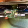
PROBLEM AREA . . . . . . WORK LIGHTS DIMMER . . . .

Looking at your board, this seems to be solely the circuitry involved with the lamp dimming.
Since you didn't give us a foil view, this is the best that I can do.
Correct me . . . . if wrong, but isn't the 7 ohm 2 watt metal film resistor, in the circuitry where I have the
VIOLET star ?
CIRCUIT DESIGN . . . . flow path
230 VAC power from the lamp switch comes in at top left corner and passes down the
RED ARROW path until it reaches the MT2 terminal of the TRIAC and is then dependent upon gate drive to complete the MT1 connection to power ground and . . .
LET THERE BE LIGHT!
Note . . .simultaneously . . . . that there is an AC power branch off, down the
GREEN ARROW path that goes down and passes thru a 10K fixed resistor to then feed into a rheostat connected 500K dimmer control pot. That path then goes into a DIAC that has to have its voltage breakdown threshold exceeded in order to let sequential 50~ narrow "
burst/choplets" of drive power to trigger the gate of the TRIAC. With the series 10 K resistance and the additional full 500K of resistance of the dimmer pot . . . . . that chopped drive power that turns on the TRIAC . . . . .is equating to about the equivalency of 60'ish volts RMS powering those 120 VAC rated lamps.
If you then rotate the dimmer pot clockwise, its resistance will ever be lowering, until only the 10K of fixed resistance is in circuit.
That results in WIDER 50 ~ "
burst/choplets" of drive power that then equates to getting ~ full 120V RMS power to the lamps.
HOWTODOITTOIT . . . . . . or . . . .
¿ What Would Edd Do ?
I would initially pull out AC metering and place negative probe to AC line neutral or MT1 and power up unit and turn on light switch and monitor TRIAC MT2 to see what level of AC voltage is being present . . . . . its full presence confirms that both lamps are not blown.
Expecting . . . . and having voltage . . . . keep negative where it was and move + probe to gate of TRIAC and take note and log voltage being read at min and max positions of the dimmer pot.
Move both probes to measure across the DIAC and log in voltages that were being read at min and max of dimmer pot positions..
Pass us back that voltage info for its evaluation . . . . .
Looks like you should be able to read the existing TRIAC part number . . .pass that on to us.
ENLIGHTENING DETAILS . . .
What I really wanted to convey to you . . . . on there being the separate and dual sets of holes on the area of the TRIAC mounting . . . . was the dual capability of using either a small TO-92 casing or the larger sized TO-202 that was used for heftier units.
Drop in either of those TRIAC casings and its foil connections are being correct..
Examine party animals blurry photo and see a thin, small slotted heat sink tab sticking up and also a side ground chamfer / key on the devices case proper.
Its not being the FULL length extension of a THICKER heat sink that a TO-220 uses.
That TO-202 style of casing was VERY-VERY much used on earlier days TRIACS and SCR's..
I'll just bet that the bean counters ( accounting / inventory ) made them use the cheaper device.
BECAUSE it only is handling the power of two
VERY LOW WATTAGE lamps.
I remember a 6S6 that was a 6 watt /120v lamp that is formed in the bulb profile of a clear glass Christmas tree light bulb of the 1940's.
Plus, they also made other low wattage lamps in that same envelope profile on up towards 10W . . . . what is yours ?
73's de Edd . . . . . .
Have you paid your taxes......??
Well ! . . . . Git 'er done ! . . . . . there are 12 million illegal aliens that are depending on your stipends.
")