FAN5345

lechik86

Jun 2, 2014
17
Joined
Jun 2, 2014
Messages
17
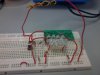
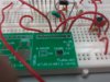
Hi everyone! How are you all doing? I'm a newbie here. I just would like to ask your opinion regarding FAN5345 function testing. What I'm actually doing is implementing the application sheet of this chip on breadboard (See attached figure), I have the exact values of the components except Rset which I replaced with 15 ohm resistor instead of 12.4 ohm. I've also decreased the number of LEDs into 6 instead of 8. I think increasing Rset is just appropriate since I used just 6 LEDs instead of 8. Also, I've added a tact switch connected to EN pin for dimming and a 0.1 uF capacitor to eliminate switch bouncing. I thought everything was all set, However when I plugged in the 5V supply for the Vin line, the LEDs didin't light up at all. By the way since I was using a breadboard to test the application of this chip I had to get a SMD to through hole adapter for this chip so I can mount it on breadboard. Here is the application schematic of the chip.

Any ideas as to why my breadboard prototype failed? :( I hope to hear from you. Thanks. :)
 

Attachments

  • FAN5345 SCHEM.png
    FAN5345 SCHEM.png
    59.8 KB · Views: 153

OLIVE2222

Oct 2, 2011
690
Joined
Oct 2, 2011
Messages
690
Hi,
The FAN5345 is running at 1.2Mhz, not sure that a breadboarded solution can work. however posting sharp picture(s) of your setup can be a good start to help you.
Olivier
 

lechik86

Jun 2, 2014
17
Joined
Jun 2, 2014
Messages
17
Hi Olivier! Okay I'll just post pictures of my setup tomorrow cause I don't have it with me right now. Thanks a lot. Hope you're still here tomorrow. :)
 

Harald Kapp

Moderator
Moderator
Nov 17, 2011
14,272
Joined
Nov 17, 2011
Messages
14,272
Two simple questions:
1) EN is set to high level? With EN permanentzly low the chip should not start up.
2) Dumb, maybe, but: All LEDs are connected with correct polarity?
 

lechik86

Jun 2, 2014
17
Joined
Jun 2, 2014
Messages
17
Hi Harald! Currently the en pin is connected to a switch. One end of the switch is connected to 5V. There is also a 0.1uF capacitor connected parallel to the switch to eliminate switch bounce.

Here is the current setup on breadboard.
 

Attachments

  • 2014-06-04 10.27.12.jpg
    2014-06-04 10.27.12.jpg
    100.6 KB · Views: 105
  • 2014-06-04 10.28.02.jpg
    2014-06-04 10.28.02.jpg
    101.2 KB · Views: 118
Last edited:

(*steve*)

¡sǝpodᴉʇuɐ ǝɥʇ ɹɐǝɥd
Moderator
Jan 21, 2010
25,510
Joined
Jan 21, 2010
Messages
25,510
I'd be a little suspicious of the inductor you're using. What ate it's specs.

The wiring is a bit "all over the place" for the frequency
 

lechik86

Jun 2, 2014
17
Joined
Jun 2, 2014
Messages
17
I've used a 10uH inductor as what's indicated on the application sheet. I've also measured it's resistance. It's just around 1 ohm. so everytime I check pin 6 and pin 1 there seems to be a continuity.
 

lechik86

Jun 2, 2014
17
Joined
Jun 2, 2014
Messages
17
Correct me if I'm wrong but from what I understand on the datasheet, this device should be able to give an output of 30V maximum if you plug in 2.5~5V on Vin. Right now what I'm getting is just 4.97V reading on Vout pin after plugging in the 5V supply.
 

(*steve*)

¡sǝpodᴉʇuɐ ǝɥʇ ɹɐǝɥd
Moderator
Jan 21, 2010
25,510
Joined
Jan 21, 2010
Messages
25,510
What are you using for D9? I hope it's not a 1N400x. It needs to be a high speed diode.

datasheet

What's this pin 0 you show on your schematic?

Are you sure you have the pins wired up correctly (they're not in the order shown on the schematic).
 

lechik86

Jun 2, 2014
17
Joined
Jun 2, 2014
Messages
17
I'm using a 1N5819 Schottky Diode which looks something like this.
1N5819-G.JPG
 

lechik86

Jun 2, 2014
17
Joined
Jun 2, 2014
Messages
17
I've already doublechecked my connections and everything seems to be connected properly.
 

lechik86

Jun 2, 2014
17
Joined
Jun 2, 2014
Messages
17
Can the chip really work with just a switch connected to it? Or should it be driven by a microcontroller?
 

OLIVE2222

Oct 2, 2011
690
Joined
Oct 2, 2011
Messages
690
This kind of cabling afraid me a bit. As your small pcb as an header I suggest to mount the parts on it with components wire length as short as possible.
The PCB picture is blurry, please post a sharp one to look at the solders. And yes the component is a step-up you should have higher output voltage than 5V
Olivier
 

lechik86

Jun 2, 2014
17
Joined
Jun 2, 2014
Messages
17
This kind of cabling afraid me a bit. As your small pcb as an header I suggest to mount the parts on it with components wire length as short as possible.
The PCB picture is blurry, please post a sharp one to look at the solders. And yes the component is a step-up you should have higher output voltage than 5V
Olivier

The datasheet of the FAN5345 states that the VIn should only range from 2.5V ~ 5V. My question is can FAN5345 really work with just a switch driving it? Or it needs a microcontroller?
 

lechik86

Jun 2, 2014
17
Joined
Jun 2, 2014
Messages
17
Actually this concept came from this schematic. I have the actual module of this design. Basically my goal is to prove that I can replace MIC3289 (which is U1 on this schematic) with FAN5345. From what I understand, the only difference of these 2 LED drivers is MIC3289 operates on 16 levels while FAN5345 operates on 32 levels. Also MIC3289 is negative edge triggered, while FAN5345 is positive edge triggered.

I've actually tried to remove the PIC microcontroller on the board and connected the DC pin of MIC3289 to a switch, a capacitor and a pull down resistor.

Is it safe to say then that it needs a microcontroller to drive the FAN5345 chip?
 

Attachments

  • ORIG SCHEM.png
    ORIG SCHEM.png
    371.2 KB · Views: 116
Last edited:

(*steve*)

¡sǝpodᴉʇuɐ ǝɥʇ ɹɐǝɥd
Moderator
Jan 21, 2010
25,510
Joined
Jan 21, 2010
Messages
25,510
Disconnect everything from pin 4. It should remain turned on like that.

Dimming is just done with PWM, this device has 2 brightness levels, on and off.

And explain pin 0 on your schematic.
 

OLIVE2222

Oct 2, 2011
690
Joined
Oct 2, 2011
Messages
690
The datasheet talk about digital pulses, so a microcontroller will be better, with a push-button you can have bouncess
 

lechik86

Jun 2, 2014
17
Joined
Jun 2, 2014
Messages
17
Disconnect everything from pin 4. It should remain turned on like that.

Dimming is just done with PWM, this device has 2 brightness levels, on and off.

And explain pin 0 on your schematic.


The actual chip doesn't have a pin 0. That schematic that has a pin 0 came from the application sheet of FAN5345.
 

OLIVE2222

Oct 2, 2011
690
Joined
Oct 2, 2011
Messages
690
sure you can try that, or any more elaborate debouching circuit.
 
Top