Flyback converter problem with MOSFET action ?

Surjitsinh

Jan 1, 2015
17
Joined
Jan 1, 2015
Messages
17
Hallo Every one ,

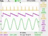
I am building flyback converter which converts High voltage AC to low voltage DC . But i have an issue MOSFET shown in scematic is turning on when input signal ( yello ) reaches negative peak , not during positive peak , what should i do ? in general Flyback configuration shows only one MOSFET . Please help.
 

Attachments

  • Typical-flyback-converter-and-Synchronous-Rectifier.jpg
    Typical-flyback-converter-and-Synchronous-Rectifier.jpg
    4.1 KB · Views: 177
  • Output with ground isssue , 6 Vpp , 2.6 DC rectified.jpg
    Output with ground isssue , 6 Vpp , 2.6 DC rectified.jpg
    55.3 KB · Views: 110

Harald Kapp

Moderator
Moderator
Nov 17, 2011
14,272
Joined
Nov 17, 2011
Messages
14,272
What are the violet and green signals?
What is the "input signal"? Do you mean the gate-source voltage? The yello signal does not show negative peaks.
Where can we see when the MOSFET is on or off?

Can you please explain in a bit more detail your signals and the problems you encounter?
 

Surjitsinh

Jan 1, 2015
17
Joined
Jan 1, 2015
Messages
17
Hallo , Thank you for replying ,

Yes , Yellow : switching signal for MOSFET , Violet : Output capacitor voltage ,Green : Input signal , Step not shown in circuit is AC - DC conversion this is represented as DC source . Now when MOSFET is Switched On and Input signal reached negative peak ; circuit transfer voltage to Output capacitor but only during negative peak , i want for both peaks ...
 

Harald Kapp

Moderator
Moderator
Nov 17, 2011
14,272
Joined
Nov 17, 2011
Messages
14,272
Show us the DC signal (represented by the battery in your 1st schematic). This is the one relevant for operation of the flyback converter, not the AC input.
 

Harald Kapp

Moderator
Moderator
Nov 17, 2011
14,272
Joined
Nov 17, 2011
Messages
14,272
This is not a flyback converter. Fora flyback converter the polarity (dots) of input and output coil of the transformer are on opposite sides (see here).
My request for the DC signal was menat to see the waveform, not the circuit diagram. It will also be interesting to see where in the circuit you actually connected your scope probes and the resoective grounds. You may have accidentally created a ground loop or short-circuit.
 

Surjitsinh

Jan 1, 2015
17
Joined
Jan 1, 2015
Messages
17
Yeah true ...Its not possible in design tool to make opposite polarity widing but i made it on breadbord the same that you showed .I am not connecting any Scope ground , only positive pins are connected .
 
Last edited:

Harald Kapp

Moderator
Moderator
Nov 17, 2011
14,272
Joined
Nov 17, 2011
Messages
14,272
I am not connecting any Scope ground , only positive pins are connected .
That way you will not get reliable measurements. You need to connect ground.
Ignore the AC input. Measure:
  1. positive suply voltage (top of primary winding)
  2. gate-source voltage of the MOSFET
  3. drain-source voltage of the MOSFET
  4. output voltage. Note that for the purpose of measuring you can connect the ground of he input side (source of MOSFET) and ground of the output side.
Note that you should also provide a snubber network across the drain-source of the MOSFET or across the primary winding of the Transformer to limit the high flyback voltage on the primary side of the coil which easily damages the MOSFET.

By the way, are you really located in Germany?
 

Surjitsinh

Jan 1, 2015
17
Joined
Jan 1, 2015
Messages
17
Thank you for your answer sir , yes i am living in Furtwangen , Schwarzwald
 
Top