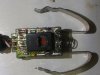
The circuit in the plug, using the KSE13003, looks like a standard emitter follower regulator with zener, but... the transistor seems to have been installed backwards! In other words it should be fitted so we can see its partly exposed metal face, not its plastic face with the part number marking!
The circuit is probably there to keep the automotive noise and spikes away from the main PCB. It will provide good protection against positive spikes but no protection against negative spikes; the addition of a diode (e.g. UF4007) between the end spring (anode end of diode) and the rest of the circuitry (cathode end of diode) would help.
Once the transistor is replaced, the output will be on the red wire, with the black wire being the 0V return.
According to your drawing, the white wire only connects to one side of C2, but I don't think that's all. Is it also connected to the black wire? It might be used as a second 0V conductor.
The output voltage is determined by the zener voltage, which we can't see. I would expect to see another regulator on the main board, taking the voltage from the red wire and dropping it down for the parts on that board, since this regulator is crude and not very accurate.