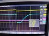
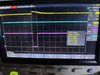
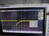
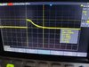
What do you see on your scope when connected to the common node of R4&R5 when you cycle 12V on/off?
It should be a ~0.7V positive pulse when 12V cycles off, and ~-0.7V negative pulse when 12V cycles on.
Generating two complementary signals on 12 V supply on/off
- Thread starter dashy1981
- Start date
")