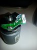
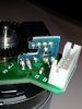
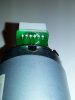
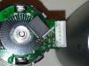
The little circuit board should help you figure it out. The big black rectangular thing is the optical encoder. This looks like it might have 4 connections, which probably connect to 4 of the pins. The other 2 are probably the motor winding. Test the resistance of the assumed motor winding. I should be in the 10s to 100s of Ohms. If so, apply 3V and see if the motor spins.
The 4 encoder pins are likely to be 2 for and LED and two for a phototransistor. You should be able to find the 2 for the LED by using say 3V and a 1K resistor and and ammeter. Look for a connection that gives you a few mA of current. The other two will be the phototranstor. It could be NPN (most likely) or PNP and the two pins are the emitter and collector. Wire it up with a 10K from one pin and the other pin to a 3V battery. You can try both polarities and both pins for the collector (the one with the 10K). One of these will give you a good signal at the collector (0V, 3V) as you rotate the shaft.
Bob
Edit: Did the seller at least give you an idea of voltage and current?