Help!! My Door Alarm is not work?

michael1983

Apr 5, 2007
8
Joined
Apr 5, 2007
Messages
8
Help..
Im doing my electronic course project...
Im choosing the door alarm project from this site.

http://www.electronics-lab.com/projects/sensors/020/index.html

1. There inductor 1 must be in 20 to 30 turns? it dont care how long the wire diameter we use?

2. the miniature inductor there is counting in mili or micro henry??

3. If i trying my circuit in breadbroad (solderless circuit board), it may be not work???

:(

 
Last edited by a moderator:

audioguru2

Apr 6, 2004
12,022
Joined
Apr 6, 2004
Messages
12,022
michael1983 said:
1. There inductor 1 must be in 20 to 30 turns? it dont care how long the wire diameter we use?
The instructions say the wire diameter to use and says exactly how to make it.

2. the miniature inductor there is counting in mili or micro henry??
The instructions say 10mH which is ten milli-Henries.
Micro-Henries is written as uH.
3. If i trying my circuit in breadbroad (solderless circuit board), it may be not work???
Most radio frequency circuits like this one do not work on a breadboard because the stray capacitance and stray inductance are too high.


MP1

Dec 7, 2003
3,397
Joined
Dec 7, 2003
Messages
3,397
michael1983 said:
There inductor 1 must be in 20 to 30 turns? it dont care how long the wire diameter we use?
Michael,
More specifically, L1 is made by wrapping (coiling) the wire around R2 until it is completely covered with the winding. This is why it says 20 to 30 turns. Different resistors will be different lengths and thickness.

MP
 

audioguru2

Apr 6, 2004
12,022
Joined
Apr 6, 2004
Messages
12,022
michael1983 said:
that mean, i cant use breadboard to try do my circuit???
"Most radio frequency circuits like this one do not work on a breadboard"
Make a pcb or use stripboard with very short wiring.
 

michael1983

Apr 5, 2007
8
Joined
Apr 5, 2007
Messages
8
oh..ok...

Sir,

1. the 10 mH inductor is so hard to get at my place here...is the size is same like other inductor in green color like resistor?

2. this site is from which country?

3. can i buy component online??

4. any other circuit recomend oscilator circuit..better can try in breadboard....

thank you.. ;)


audioguru2

Apr 6, 2004
12,022
Joined
Apr 6, 2004
Messages
12,022
michael1983 said:
1. the 10 mH inductor is so hard to get at my place here...is the size is same like other inductor in green color like resistor?[/quote[
A 10mH miniature inductor is available in electronic parts stores and online.


The owner is Greek but the site has members from all over the world.


I usually order electronic parts online. If i place an order before 8:00 PM then it is delivered the next morning. I usually order from www.digikey.com but there are hundreds more sites.
 

audioguru2

Apr 6, 2004
12,022
Joined
Apr 6, 2004
Messages
12,022
michael1983 said:
1. what is the value of 2 capacitor? it write in 2^2 and 100^ is mean what????
Our projects section has a problem printing Greek letters on schematics.
Look at the original project: http://www.redcircuits.com/Page54.htm

2u2 is 2.2uF.
 

michael1983

Apr 5, 2007
8
Joined
Apr 5, 2007
Messages
8
The hook inside the circuit must use brass??

Can i use any single core wayar and cut off the PVC insulator cover???


audioguru2

Apr 6, 2004
12,022
Joined
Apr 6, 2004
Messages
12,022
michael1983 said:
The hook inside the circuit must use brass??
Brass, copper or even gold will conduct well for the hook.

Can i use any single core wayar and cut off the PVC insulator cover???
Wayar won't work. Use wire. It must have any insulation removed.
 

michael1983

Apr 5, 2007
8
Joined
Apr 5, 2007
Messages
8
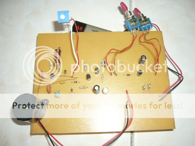
my circuit is not work...help!!


P1100047.jpg


P1100048.jpg


1. when i open switch 2...the buzzer and LED will sound and light 2gether...Switch still close.

2. my trimet is set to the low point, the LED still like....

wat happen?
wat troubleshooting step should i take?

 
Last edited by a moderator:

audioguru2

Apr 6, 2004
12,022
Joined
Apr 6, 2004
Messages
12,022
The parts are too far apart on your pcb. The wires to the switches and trimpot are much too long. The distance between parts and the long wires adds too much stray capacitance and inductance which is not wanted in this radio circuit.
Check the datasheets for the transistors to see if you connected their pins backwards.


michael1983

Apr 5, 2007
8
Joined
Apr 5, 2007
Messages
8
tat mean my redo my PCB board?

My transistor connection is ok....

when i solder can my solder hot damage my component??

how can i troubleshoot it?


audioguru2

Apr 6, 2004
12,022
Joined
Apr 6, 2004
Messages
12,022
I think your circuit doesn't work because the pcb is too big.
Radio circuits like this one must be small so that stray capacitance and stray inductance are small.

My soldering iron is temperature controlled so that it never gets too hot. A solder joint takes only 2 seconds so the parts don't have enough time to heat much.

 
Top