Help with LM386 Amp Circuit

McDroogie

Dec 25, 2012
37
Joined
Dec 25, 2012
Messages
37
I cannot troubleshoot this lm386 circuit. I believe I have wired everything accordingly to the schematic and I have posted it as well as the breadboard and its components. Could someone please tell me if I am missing anything?
 

Attachments

  • IMG-20121231-00159.jpg
    IMG-20121231-00159.jpg
    37 KB · Views: 221
  • IMG-20121231-00158.jpg
    IMG-20121231-00158.jpg
    161.9 KB · Views: 254
  • IMG-20121231-00157.jpg
    IMG-20121231-00157.jpg
    100.2 KB · Views: 265
  • IMG-20121231-00156.jpg
    IMG-20121231-00156.jpg
    154 KB · Views: 288

quantumtangles

Dec 19, 2012
153
Joined
Dec 19, 2012
Messages
153
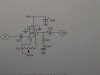
Find the datasheet for LM386 ICs on Google. Check that all 8 pins on the datasheet correspond with the pin connections in your schematic. If you are sure you have got the pin connections correct (note the orientation of the IC), the next thing I would check is your power supply.

If you are using a battery, check the voltage of the battery with a multi-meter.

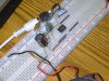
If the power supply is delivering the expected voltage to the breadboard, next up I would check that your audio signal is actually arriving onto the breadboard. You might be able to check this with a crystal radio earpiece or even a multi-meter, but be sure that the signal you aim to amplify is actually present.

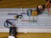
If all the above checks out, I would check that the speaker is working by testing it independently of the circuit you are now building. Does the speaker work or not.

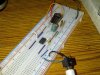
Next up I would check the resistance of the carbon film resistor in Ohms with a multi-meter. If the value is correct, I would check that the variable resistor (the potentiometer) has the required value range as well. That 221 ceramic cap...how does it fit into the circuit. Looks out of place here. Have you used a ceramic cap where the circuit requires an electrolytic 220uF capacitor...cant see clearly.

I would bet it is a power supply/speaker/signal issue. Is any power getting to the speakers. If not, why not. Is voltage appearing everywhere in the circuit where you would expect it to appear? You should at least hear crackling when you power up the IC if the power supply and speaker are correctly connected. That is where I would concentrate. My best guess is that your speaker is not receiving any power. More exotic explanations might include the possibility that the IC is damaged (some ICs cannot survive incorrect pin connection and just die). I do not think you have a problem with your electrolytic capacitors judging by their appearance, but you never know. Replace candidate components if you are unsure about them.

I hope this check list approach is of some help pending a more expert response from electronic engineers here who know a lot more than I do about these things.
 
Last edited:

davenn

Moderator
Sep 5, 2009
14,470
Joined
Sep 5, 2009
Messages
14,470
QT

its not really an Op-Amp per se

it is a dedicated audio amplifier IC

I was tempted to go through your post and delete all references to Op-Amp, maybe you would like to do that ?
 

davenn

Moderator
Sep 5, 2009
14,470
Joined
Sep 5, 2009
Messages
14,470
Hi McDroogie

welcome to the forums :)

comparing your circuit to the one in the datasheet, the first error I notice is that you have the input on the incorrect pin.
try grounding pin 2 and inputting to pin 3

your main volume control (gain) shouldnt be a variable between pins 1 and 8
those pins are to set a fixed gain. eg. pins 1 and 8 unconnected gain = 20
pin 1 to pin 8 via a 1k2 resistor and a 10uF cap ... gain = 50

your main volume control should be a variable pot on the input to pin 3 either before or after your 0.01uF cap. That cap also seems a bit small, try increasing it to ~ 1uF

it ALWAYS pays to check the datasheet for good information on the use of any device :)

Dave
 

McDroogie

Dec 25, 2012
37
Joined
Dec 25, 2012
Messages
37
Thanks a lot? So change the input cap from a disc cap to an electrolytic 1 uf? And another question could I place a 25k ohm pot?
 

davenn

Moderator
Sep 5, 2009
14,470
Joined
Sep 5, 2009
Messages
14,470
OK after looking at the breadboard layout
you have some wires going nowhere ... like the 2 purple wires off pin 1 and 8
you have added lots of extra and unneeded wires that only complicate the layout
eg ....
your green input wire goes to a blue wire then to the 0.01 cap ... get rid of the blue wire and take the green wire straight to the cap

you have a green wire off the output capacitor to the red wire of the speaker
get rid of the green wire and just put the red speaker wire straight to the capacitor

you have a blue wire off pin 6 going to the green electrolytic, the other side of that electro is going to a green wire and onto that disc ceramic .... that isnt correct
the negative of that green electro should be going to your gnd rail ( where your power black is connected) ...
so rotate the green link wire 90 deg to connect it to the gnd rail

finally rotate that disc ceramic cap 90 deg so the end opposite to the 10 Ohm resistor also goes to the gnd rail

Dave
 

davenn

Moderator
Sep 5, 2009
14,470
Joined
Sep 5, 2009
Messages
14,470
Thanks a lot? So change the input cap from a disc cap to an electrolytic 1 uf? And another question could I place a 25k ohm pot?

yes

and yes you could use a 25k pot on the input. one side terminal of pot to gnd rail other side to input signal and the centre terminal to the 1uF electro and the other side of the electro to pin 3

DONT forget to GND pin 2 instead of pin 3

you could remove those 2 purple wires off pins 1 and 8 and that as I said above will set the internal gain at 20


Dave
 

Relayer

Dec 15, 2012
39
Joined
Dec 15, 2012
Messages
39
That disc ceramic cap is only 220pF. I doubt that's going to help.
Regards,
Relayer :D
 

Relayer

Dec 15, 2012
39
Joined
Dec 15, 2012
Messages
39
Why is this? it calls for a .047 cap, would a 220 cap be better?
The capacitor you used is 220pF (p = picofarads) i.e 220 picofarads.
The 0.047uF cap in picofarads would be 47,000pF... See the difference?
The disc ceramic is way too low in value.
Regards,
Relayer :D
 

Harald Kapp

Moderator
Moderator
Nov 17, 2011
14,271
Joined
Nov 17, 2011
Messages
14,271
Why is this? it calls for a .047 cap
but you haven't used 0.047µF, but 0.000220µF.
Why should this be better? Also, as Dave has noted, there are these 2 wires from 1 and 8 that in the schematic go to a potentiometer. Your breadboard doesn't show that potentiometer.
 
Last edited:

McDroogie

Dec 25, 2012
37
Joined
Dec 25, 2012
Messages
37
but you haven't used 0.047µF, but 0.000220µF.
Why should this be better? Also, as Dave has noted, there are these 2 wires from 1 and 8 that in the schematic go to a potentiometer. Your breadboard doesn't show that potentiometer.

Because bigger is better?
 

Harald Kapp

Moderator
Moderator
Nov 17, 2011
14,271
Joined
Nov 17, 2011
Messages
14,271
Because bigger is better?
Not necessarily so.

First you have to get your exponents right:
µ ^= 10^-6
n = 10^-9
p = 10^-12
so 220pF is about a factor 200 smaller than 0.047µF.

Second: Each component has it's function. Overfunction is as bad as underfunction. Therefore you should use the recommended component values unless unless you want to change the function and you know what to do and how to do it.
 

McDroogie

Dec 25, 2012
37
Joined
Dec 25, 2012
Messages
37
Is there an equation that could help get the audio frequencies based on the input and output capacitance?
 

Harald Kapp

Moderator
Moderator
Nov 17, 2011
14,271
Joined
Nov 17, 2011
Messages
14,271
It is not only the capacitances that matter but the resistances and the frequency response of the amplifier chip, too.
Look up the datasheet or an application note for the chip. You should find the relevant information there.
 

McDroogie

Dec 25, 2012
37
Joined
Dec 25, 2012
Messages
37
Now if I replace the disc cap in the input with a 1uf electrolytic cap, how do I determine where the positive lead goes?
 

davenn

Moderator
Sep 5, 2009
14,470
Joined
Sep 5, 2009
Messages
14,470
the positive goes towards the input signal

D
 

McDroogie

Dec 25, 2012
37
Joined
Dec 25, 2012
Messages
37
Thank you all for your help. I completed it on some ic board. Now the only problem I'm having now is that I get some crackle from the speaker. Could it be from improper soldering or what?
 

davenn

Moderator
Sep 5, 2009
14,470
Joined
Sep 5, 2009
Messages
14,470
Thank you all for your help. I completed it on some ic board. Now the only problem I'm having now is that I get some crackle from the speaker. Could it be from improper soldering or what?

show us a new photo or 2 of the board so we can see if you did all the mod's correctly
did you use a solder proto board ?

if so why didnt you for a start just mod things on the breadboard and get it working before transferring to a more permanent soldered board ?

take a step back :)

Dave
 
Top