Heyelp! Tapco S5 active monitor problem

Old-Bugga

Sep 14, 2014
7
Joined
Sep 14, 2014
Messages
7
I picked up a pair of Tapco S5 active monitors. The seller made it clear one had a fault.

Fault is that when one speaker is switched on it buzzes loudly and the larger speaker can be seen to pull inwards.

Video showing the fault can be viewed here:-


I am at a basic level with electronics. I can solder, and have a meter if required. My usual plan of attack is visual and being a board jockey.

I removed the electronics side and thought I had found the fault. Looked very like I had a leaky capacitor as there was a build up of fluffy crud around the base of one. Replaced this and it's still the same.

Swapped the full panel from the good speaker and no buzzing, however, I am pretty sure the tweeter is blown as sound was very dull and zero sound compared to the known good speaker.

Transformers on both speakers work fine.

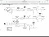
So.....I know the problem is on this board but where? At this point I am out of my depth.

Could I ask you guys what you reckon the most likely part to fail may be?

The Bridge Rectifier is part no KBL406
Looks to be an amplifier chip for the low frequency and high frequency sides. Same part no for both is LM3886T.
 

Attachments

  • image.jpg
    image.jpg
    218.3 KB · Views: 300
  • image.jpg
    image.jpg
    164.7 KB · Views: 271

KrisBlueNZ

Sadly passed away in 2015
Nov 28, 2011
8,393
Joined
Nov 28, 2011
Messages
8,393
Hi there and welcome to Elecronics Point :)

Most likely the LM3886 will be the fault. These are available from Farnell fairly cheaply - see http://uk.farnell.com/texas-instruments/lm3886t/amp-audio-mute-68w-3886-to-220/dp/9493603

(BTW thanks for putting your location in your profile. It tells us which supplier to recommend.)

Before we assume the LM3886 is faulty, you should disconnect the speakers and measure the voltages on all pins using a multimeter. Connect the black probe of the multimeter to the 0V rail - you can get this on the outer metal of the RCA socket, or the jack socket, and various other places in the circuit, including pin 7 of the LM3886 itself.

Measure the voltage on each pin with the red probe. Be very careful not to let the probe slip and short two adjacent pins together. It's best to measure them on the underside of the board, where you can probe them directly from "above". Here is the pinout from the data sheet:

lm3886 pinout.png

Here's the "typical application circuit" from the data sheet:
lm3886 application circuit.png

The voltages on the pins should be:
1: positive supply voltage
2: no connection (no need to measure)
3: output (should be 0V but probably isn't)
4: negative supply voltage
5: positive supply voltage
6: no connection (no need to measure)
7: 0V
8: mute input; will probably be slightly negative
9: inverting input; will probably be the same voltage as the output
10: non-inverting input; should be 0V
11: no connection (no need to measure)

The positive and negative supply voltages should be of opposite polarity (the meter will show a negative sign when you measure the negative rail) and should have roughly the same voltage.

If you post all the measured values we can go from there.
 

Old-Bugga

Sep 14, 2014
7
Joined
Sep 14, 2014
Messages
7
Thanks, will get onto this tomorrow when I can get to my meter.
 

Old-Bugga

Sep 14, 2014
7
Joined
Sep 14, 2014
Messages
7
Here is what I got.

The voltages on the pins should be:
1: positive supply voltage 13.1
2: no connection (no need to measure)
3: output (should be 0V but probably isn't) 0
4: negative supply voltage 0
5: positive supply voltage 10.7
6: no connection (no need to measure)
7: 0V
8: mute input; will probably be slightly negative 0
9: inverting input; will probably be the same voltage as the output 0
10: non-inverting input; should be 0V 0
11: no connection (no need to measure)
 

KrisBlueNZ

Sadly passed away in 2015
Nov 28, 2011
8,393
Joined
Nov 28, 2011
Messages
8,393
OK, they're all wrong!

Pins 1 and 5 should be connected together. I don't know how they can measure different voltages. Could you check that please? Measure resistance between the pins to check that they're connected together, then re-measure the voltages.

The negative supply rail seems to be missing. This explains why the mute input on pin 8 is not slightly negative.

In the first picture in post #1, just between the two large blue cylindrical electrolytics and the bottom of the curved edge for the speaker magnet, there's a 3-pin connector, and a black device that is stuck onto one of the electrolytics with white "binding snot". The 3-pin connector connects to the power transformer, right? Can you see any markings on it? You can cut away the snot if necessary.

Also have a look in that area for any damage to the tracks on both sides of the board.
 

Old-Bugga

Sep 14, 2014
7
Joined
Sep 14, 2014
Messages
7
I think you are describing the bridge rectifier. I gave that part no KBL406.

Tried again (this meter seems to have the better of me). I put the black leg on pin 7 and got the following readings.

I have no speakers attached and the mains connected/on

1 0.2
3 0
4 0
5 0.3
8 0
9 0
10 0
 

Attachments

  • photo.JPG
    photo.JPG
    47.9 KB · Views: 203

KrisBlueNZ

Sadly passed away in 2015
Nov 28, 2011
8,393
Joined
Nov 28, 2011
Messages
8,393
Ah, so you did, sorry. I'm helping several different people at once and it's hard to keep track of their level of knowledge!

Yes, I suspect the bridge rectifier. It could have caused the electrolytic to pop as you described. Which electrolytic did that? Is it in the area in the second photo? I can't really make out what's happened there.

I suggest you remove the bridge rectifier and measure it on your meter's diode range, if it has one. Otherwise just check for continuity between pins. You know how to test a bridge rectifier? If not, Google it, it's pretty straightforward.

If the bridge is shorted, the large electrolytics may have been damaged. The amplifiers could have been damaged too. Also, is the thing still making the buzzing noise: I hope so - if that's stopped, it could be because the mains transformer has failed, or popped its thermal fuse, because of the overload.
 

Old-Bugga

Sep 14, 2014
7
Joined
Sep 14, 2014
Messages
7
Yes, the one shown in the second photo. There was a lot of white furr around the base of the cap.
For all they costs I would just try replacing the BR. Doubting my testing abilities with this meter.
One of the large electrolytics is giving a zero reading whereas the other slowly rises to around 6000 which looks to be around the correct value 6800. The other just reads zero.
 

KrisBlueNZ

Sadly passed away in 2015
Nov 28, 2011
8,393
Joined
Nov 28, 2011
Messages
8,393
One of the large electrolytics is giving a zero reading whereas the other slowly rises to around 6000 which looks to be around the correct value 6800. The other just reads zero.
That sounds like there's something wrong apart from the bridge rectifier. Unless you measured that with the transformer plugged in.

Take out the bridge rectifier and unplug the transformer, and measure resistance across the two big electrolytics again. If either of them measures short circuit, it could be the electrolytic itself, but more likely to be one or both of the output ICs.

It would be interesting to know more about the electrolytic that everted itself. I can't really make it out from the photo. Could you post another one, taken at a slight angle? While you're at it, a photo of the underside could be useful too.

Edit: What range were you using to measure the electrolytics? If you're measuring their capacitance, you probably need to lift one end of the electrolytic out of the board, so you're measuring it out-of-circuit. You can measure them on resistance range too; the reading starts small but increases as the electrolytic charges up. This is the way to test for a short circuit. You can do this with the electrolytic in-circuit but if you read a short circuit (less than a few ohms), you can't tell whether it's the electrolytic or something else in the circuit, unless you lift one end.
 

Old-Bugga

Sep 14, 2014
7
Joined
Sep 14, 2014
Messages
7
Yes and no. Replaced both amp chips, both large capacitors and the bridge rectifier and now the unit doesn't even power up. Waved the White flag of surrender and passed it over to a local repair guy. Just waiting to hear what he finds. Will post an update once I hear from him. Thanks for your help.
 
Top