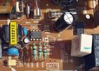
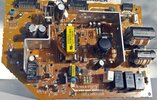
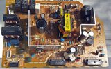
I have a Hitachi 57F710E Rear Projection TV that was working great until about a month ago. I came in and tried to turn it on and it was just dead. So, I unplugged it and plugged it back in. Nothing, not even the slight click that it makes when you plug it in. So, I removed the power supply board (It's a vertically mounted board, I believe model HA01312) and inspected it visually for bulged caps or burnt or overheated components, anything that didn't look right and couldn't find anything.
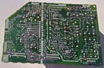
I noticed on the bottom of the board there was a row of solder joints with voltages printed next to them (10.5v, Gnd, Gnd, 5.6v, 5.6v, Gnd, 16.5v (not used), Audio Gnd, Audio), which are coming from the large transformer on top. I checked all of these voltages and they're all reading 0 volts DC.
There are 3 glass fuses that I checked and they're all fine, and 2 pico fuses (E940, E941) on the secondary side of the board that I checked for continuity while in circuit and there was continuity, there may be more fuses but I don't see any. While checking for DC voltage off of the small bridge rectifier (D901) on the primary side, I short circuited it and had to replace it. But there is approximately 108 to 115 volts DC coming off of the new rectifier, it's fluctuating real bad. If I remove the glass fuse inline right after the DC positive leg of the rectifier, I get a reading of 113.3 to 113.4 volts DC with very little fluctuation. There is approximately 120 volts AC going into the rectifier. So, I assume there is something wrong after the rectifier. There is a larger capacitor after the fuse and I believe some kind of switching chip or IC offline switch flyback after that (I901) chip # A6159. And a few other caps, resistors, and a small transformer. Perhaps the problems lies within one of these components.
I would really appreciate any help anyone could give me in fixing this issue. It's an old TV but it still has a great picture and I would prefer to fix it if I can.
Thanks