How to Select Connector Contacts: A Practical Guide to Pins, Sockets, Wire Gauge, Plating, and Termination
Meta Description:Learn how to select connector contacts based on housing compatibility, contact type, wire gauge, termination method, plating, electrical ratings, tooling requirements, and product lifecycle status.
Introduction
Connector contacts are the conductive elements inside an electrical connector system. They create the electrical path between wires, printed circuit boards (PCBs), and mating connector interfaces. Depending on the connector design, a contact may be a pin contact, socket contact, crimp contact, solder contact, PCB terminal, or another specialized contact type.
Although connector contacts are sometimes broadly called terminals, the two terms are not always interchangeable. In connector datasheets and application specifications, a contact usually refers to the individual conductive component installed in a connector housing, while a terminal may refer more generally to a wire-termination or PCB-termination component.
Selecting the correct connector contact requires more than matching a pin or socket to a connector housing. Engineers, procurement teams, and assembly teams must verify compatibility among the connector series, housing part number, cavity design, contact type, wire gauge, insulation diameter, termination method, plating, electrical ratings, operating environment, and assembly tooling.
For rectangular connector contacts, the most important selection rule is to begin with the manufacturer, connector series, and compatible housing. A contact that appears physically similar may still be incompatible because of differences in contact orientation, locking-lance geometry, retention shoulder position, cavity dimensions, mating interface, or crimp requirements.
This guide explains what connector contacts are, the major types of pin and socket contacts, available termination methods, and the key technical factors to evaluate before selecting contacts for wire-to-wire, wire-to-board, PCB-mounted, panel-mounted, or free-hanging connector assemblies.
What Are Connector Contacts?
Connector contacts are conductive components that carry electrical current or signals through a connector system. A typical connector assembly consists of a housing, one or more contacts, a mating connector interface, and—depending on the application—accessories such as seals, backshells, strain-relief components, retention clips, or connector position assurance devices.A connector contact is normally inserted into a dedicated cavity in the connector housing. Its mating end interfaces with a corresponding pin or socket contact, while its termination end connects to a wire, PCB, or other conductor. The contact must provide reliable electrical performance while remaining mechanically retained in the housing throughout insertion, mating, unmating, vibration, temperature cycling, and service operations.
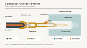
In many connector systems, the contact includes the following functional areas:
- Mating area: The portion that engages with the corresponding pin or socket contact to establish the electrical connection.
- Contact body: The main structural section that supports the contact geometry and current path.
- Retention feature: A locking lance, retention clip, shoulder, or similar feature that holds the contact in the housing cavity.
- Termination end: The area used to terminate a wire, PCB, or other conductor through crimping, soldering, IDC, PC tail, wire wrap, press-fit, or another method.
- Wire barrel and insulation barrel: For crimp contacts, the wire barrel crimps onto the stripped conductor, while the insulation barrel supports the wire insulation and helps reduce mechanical stress.
Connector Contacts vs. Terminals
In practical engineering use, “connector contact” and “terminal” are often used interchangeably. However, connector manufacturers may use these terms differently in datasheets, product specifications, and application specifications.
| Term | Typical Meaning | Common Examples |
| Connector contact | An individual conductive part installed in a connector housing and designed to mate with another contact | Pin contact, socket contact, receptacle contact, plug contact |
| Terminal | A broader term for a conductive component used to terminate a wire, PCB trace, stud, busbar, or connector interface | Crimp terminal, ring terminal, spade terminal, PCB terminal, connector terminal |
| Connector contact terminal | A term sometimes used for a contact that combines a connector mating interface with a wire or PCB termination function | Crimp pin, crimp socket, solder contact, PC-tail contact |
When selecting a part, always follow the terminology used in the manufacturer’s documentation. The relevant datasheet, product specification, application specification, and customer drawing determine whether a component is listed as a contact, terminal, pin, socket, plug contact, or receptacle contact.
Signal Contacts vs. Power Contacts
Connector contacts may be designed for signal transmission, power delivery, or specialized applications. The difference is not determined solely by contact size; it also depends on conductor range, contact material, plating, mating geometry, contact resistance, allowable temperature rise, and the connector system’s overall rating.| Contact Type | Primary Function | Typical Selection Considerations |
| Signal contacts | Carry low-current control, sensing, communication, or logic signals | Contact resistance, signal integrity, pitch, mating cycles, plating, wire gauge, crosstalk, impedance, and shielding requirements |
| Power contacts | Carry higher current for power distribution or load connections | Current rating, wire gauge, conductor area, temperature rise, contact resistance, derating, plating, crimp quality, and operating temperature |
| Specialized contacts | Support RF, high-speed data, fiber optic, USB, coaxial, or other application-specific interfaces | Impedance, bandwidth, insertion loss, return loss, shielding, optical alignment, mating interface, and system-specific requirements |
Signal contacts are often used in control circuits, sensors, communication interfaces, and low-current electronic assemblies. Power contacts are typically used in power supplies, industrial equipment, automotive systems, appliances, battery connections, and other applications where current capacity and thermal performance are critical.
A connector housing may support both signal and power contacts, but the contact cavity, size, retention design, and electrical limits must be verified for each position. Do not assume that all cavities within the same housing accept the same contact type or wire range.
For any connector system, the final contact selection should be based on the manufacturer’s product specification and application specification—not on visual similarity alone. Housing compatibility, cavity geometry, contact orientation, locking-lance design, wire range, termination requirements, and approved tooling must all match the documented connector system requirements.
Common Types of Connector Contacts
Connector contacts are available in multiple forms to support different connector housings, mating interfaces, wire sizes, current levels, PCB configurations, and assembly processes. The most common types include pin contacts, socket contacts, machined contacts, stamped-and-formed contacts, signal contacts, power contacts, and specialized contacts.Pin Contacts and Socket Contacts
A pin contact has a protruding mating end that inserts into a corresponding socket contact. A socket contact has a receptacle-style mating interface designed to accept and maintain contact pressure around a pin.Pin and socket contacts are typically used together in plug-and-receptacle, header-and-cap, wire-to-wire, and wire-to-board connector systems. Depending on the manufacturer’s terminology and connector series, they may also be described as male and female contacts, plug contacts and receptacle contacts, or header contacts and cap contacts.
For a connector-level overview of which connectors use pins, see the related guide before narrowing the choice to a specific housing-compatible contact.
| Contact Type | Mating Function | Typical Application |
| Pin contact | Provides the protruding mating interface | Plug connectors, headers, male connector interfaces |
| Socket contact | Receives the pin and provides spring contact force | Receptacle connectors, caps, female connector interfaces |
| Plug contact | Used in a plug housing, depending on the connector series | Wire-to-wire and wire-to-board plug assemblies |
| Receptacle contact | Used in a receptacle housing, depending on the connector series | Mating receptacle assemblies and panel-mounted interfaces |
The terms pin and socket describe the mating interface, while plug and receptacle often describe the connector housing or assembly role. These descriptions do not always correspond directly. For example, a plug housing may use socket contacts in one connector series, while another series may use pin contacts in its plug housing.
Before selecting a pin or socket contact, verify the following items in the manufacturer’s documentation:
- Connector series
- Housing part number
- Contact part number
- Pin, socket, plug, or receptacle designation
- Compatible wire gauge and insulation diameter
- Contact cavity position and orientation
- Applicable product specification and application specification
Machined Contacts vs. Stamped-and-Formed Contacts
Connector contacts are commonly manufactured using either machining or stamping-and-forming processes. Each construction type has different performance, cost, packaging, and tooling considerations.| Contact Type | Machined Contacts | Stamped-and-Formed Contacts |
| Manufacturing process | Produced by machining material into the required geometry | Produced by stamping sheet metal and forming it into the final shape |
| Typical geometry | Often round, precision-shaped, or designed for larger contact sizes | Often flat, box-shaped, blade-style, or spring-style geometries |
| Common applications | Circular connectors, high-reliability systems, harsh environments, larger-gauge power contacts | High-volume wire harnesses, rectangular connectors, appliance connectors, industrial equipment |
| Wire range | Often supports larger wire sizes, depending on the series | Commonly used for small- to medium-gauge wires, depending on the series |
| Packaging | Frequently supplied as loose-piece contacts | Often supplied in strip-form or tape-and-reel packaging for automated crimping |
| Tooling | May use hand tools or series-specific crimp tools | Often supports applicators and automated crimping equipment |
| Cost profile | Typically higher because of material use and machining operations | Often more economical for high-volume production |
Machined contacts are commonly selected when precision geometry, robust mechanical construction, larger conductor sizes, or demanding environmental performance is required. They may be used in circular connector systems, industrial controls, aerospace-related applications, and high-current interconnects.
Stamped-and-formed contacts are widely used in rectangular connector systems because they can be produced efficiently at high volume. Many crimp contacts used in wire harness manufacturing are stamped-and-formed and supplied on reels for use with semi-automatic or fully automatic crimping equipment.
The final selection must still be based on the approved connector series. Do not substitute a machined contact for a stamped-and-formed contact, or vice versa, unless the manufacturer explicitly identifies it as compatible with the housing, mating contact, wire range, and application requirements.
Signal, Power, and Specialized Contacts
Connector contacts can also be categorized by their electrical and functional purpose.| Contact Category | Primary Use | Typical Examples |
| Signal contacts | Low-current control, sensing, switching, and data signals | Sensor wiring, industrial control I/O, appliance control boards, low-voltage electronics |
| Power contacts | Higher-current power transmission and load connections | Power supplies, motors, battery systems, industrial equipment, appliances |
| Coaxial contacts | RF and controlled-impedance signal transmission | RF modules, antennas, test equipment, communication systems |
| High-speed contacts | High-frequency or high-data-rate differential and single-ended signals | Data backplanes, communications equipment, computing systems |
| USB contacts | USB signal and power interfaces | Consumer electronics, embedded systems, industrial devices |
| Fiber optic contacts | Optical signal transmission | Telecommunications, data communications, industrial optical systems |
Signal contacts are generally optimized for stable, low-resistance electrical connections in low-current circuits. Depending on the application, their selection may also require consideration of pitch, signal integrity, dielectric properties, shielding, impedance control, and mating cycles.
Power contacts are designed to carry higher current and usually accommodate larger conductor sizes. When selecting a power contact, verify the rated current under the actual wire gauge, ambient temperature, number of energized adjacent circuits, contact resistance, termination resistance, and temperature-rise conditions specified by the manufacturer.
Specialized contacts must be selected as part of a complete interconnect system. For example, coaxial and high-speed contacts may require a specific housing, insert arrangement, cable type, shielding method, impedance-controlled geometry, and termination process. Fiber optic contacts require compatible fiber type, ferrule geometry, polishing requirements, insertion-loss limits, and inspection criteria.
A rectangular connector housing may contain signal contacts, power contacts, or both. However, every contact position must be checked against the housing drawing, cavity design, connector product specification, and applicable assembly documentation before final selection.
Connector Contact Termination Methods
Connector contacts use different termination methods to connect a wire, PCB, or other conductor to the connector system. Common options include crimp termination, solder termination, PC tail, insulation displacement contact (IDC), wire wrap, and press-fit termination.The correct termination method depends on the connector series, contact design, wire type, production volume, installation environment, PCB mounting method, approved tooling, and requirements defined in the manufacturer’s product specification and application specification.
Crimp Contacts
A crimp contact is terminated by mechanically compressing designated contact barrels around a wire. In most crimp-contact designs, the conductor is secured by the wire barrel, while the insulation is supported by a separate insulation barrel.Crimp contacts are widely used in wire harnesses, wire-to-wire connectors, wire-to-board connectors, industrial control systems, appliances, automotive assemblies, and other applications requiring repeatable production and reliable mechanical retention.
A typical crimp contact includes the following features:
- Mating end: The pin or socket interface that mates with the corresponding contact
- Contact body: The structural section of the contact between the mating end and termination area
- Wire barrel: The section crimped onto the stripped conductor
- Insulation barrel: The section crimped around the wire insulation for strain relief
- Locking lance: The retention feature that locks the contact into the housing cavity
- Orientation feature: A geometry feature that ensures the contact is installed in the correct direction
- Bellmouth: The flared entry at the wire-barrel opening, which helps prevent conductor damage during crimping
- Cutoff tab: The residual tab created when a stamped contact is separated from its carrier strip
Before selecting a crimp contact, verify:
| Selection Item | What to Verify |
| Connector series | Confirm that the contact belongs to the intended manufacturer and connector family |
| Housing part number | Verify that the contact is approved for the specific plug, receptacle, header, or other housing |
| Contact type | Confirm pin, socket, plug contact, receptacle contact, signal contact, or power contact configuration |
| Wire gauge | Verify the approved AWG or mm² conductor range |
| Insulation diameter | Confirm that the insulation barrel supports the actual outside diameter of the wire insulation |
| Wire strip length | Use the strip length defined in the application specification |
| Crimp dimensions | Meet the specified crimp height and, where applicable, crimp width |
| Packaging format | Confirm whether loose-piece contacts, strip-form contacts, or reel contacts are required |
| Tooling | Use the specified crimp tool, die set, hand tool, or applicator |
| Pull-force requirement | Verify the required mechanical pull-force performance for the termination |
When sourcing crimp contacts and terminals through Unikeyic, start with the manufacturer part number, wire gauge range, and compatible housing.
Crimp contacts may be supplied as loose-piece contacts for manual or low-volume assembly, or as reel contacts for semi-automatic and fully automatic crimping. Reel packaging is commonly used with applicators, while loose-piece contacts are often used with hand tools, bench crimpers, or repair operations.
Crimp geometry may be described as an F-crimp, O-crimp, or another manufacturer-specific configuration. The acceptable crimp profile must always be evaluated according to the applicable connector-series documentation.
Solder Contacts
A solder contact uses solder to electrically and mechanically connect a conductor to the contact termination area. Solder contacts may be used for wire termination, PCB termination, or connector designs with solder cups, solder tails, or other solderable features.Solder termination is commonly found in connector assemblies where field installation, repairability, low production volume, specialized cable construction, or specific mechanical configurations make crimping less practical.
Common solder-contact configurations include:
- Solder-cup contacts: Contacts with a cup-shaped termination area designed to receive a stripped wire and solder
- Solder-tail contacts: Contacts with a tail designed for soldering to a PCB or another conductive structure
- PCB header contacts: Pin or socket contacts soldered into a PCB header or board-mounted connector
- Wire-to-board solder contacts: Contacts or terminals used to connect wires to PCB-mounted connector interfaces
The product specification and application specification should define the approved soldering process and any applicable limitations. Do not assume that a crimp contact can be soldered, or that a solder contact can be used with a crimp process, unless the manufacturer explicitly permits it.
PC Tail, IDC, Wire Wrap, and Other Options
In addition to crimp and solder termination, connector contacts may use specialized termination methods for PCB assembly, wire harness production, or high-volume manufacturing.| Termination Type | Description | Typical Application Considerations |
| PC tail | A contact tail designed for PCB mounting, usually through-hole or surface-mount depending on the connector design | PCB thickness, finished-hole size, tail length, solder process, board layout |
| IDC | An insulation displacement contact that terminates a wire by displacing the insulation and making contact with the conductor | Wire type, conductor construction, insulation material, insertion force, applicable wire range |
| Wire wrap | A square or rectangular post around which a stripped wire is tightly wrapped | Wire-wrap tool, post dimensions, wire gauge, wrap count, service conditions |
| Press-fit | A compliant pin or termination feature inserted into a plated-through PCB hole without solder | PCB finished-hole diameter, plating thickness, insertion force, retention force, board material |
| Solder cup | A cup-shaped contact termination used for soldering a stripped wire | Wire diameter, cup volume, solder process, heat exposure, strain relief |
PC-tail contacts are commonly used in board-mounted connectors, including wire-to-board and board-to-board interconnects. Their selection requires verification of PCB thickness, board hole diameter, pad design, soldering method, and connector mounting configuration.
IDC contacts are often used for terminated discrete wires or ribbon cables. They can improve assembly speed because stripping may not be required, but they must be matched carefully to the wire type, insulation thickness, conductor construction, and approved termination tooling.
Wire-wrap contacts are used in applications where wires are mechanically wrapped around posts to create a gas-tight electrical connection. Although less common in many modern production designs, wire-wrap termination may still be used in legacy systems, prototypes, service equipment, and specialized electronic assemblies.
Press-fit contacts are designed for solderless PCB insertion. They rely on compliant-zone deformation and controlled interference with the plated-through hole. PCB hole dimensions, plating thickness, insertion equipment, and board stack-up must be verified carefully to prevent PCB damage or inadequate retention.
Crimp vs. Solder
Crimp and solder are both established connector termination methods, but they have different process controls, tooling requirements, production characteristics, and failure modes.| Selection Factor | Crimp Termination | Solder Termination |
| Connection method | Mechanical compression of the contact around the conductor | Metallurgical bond formed by solder between the conductor and contact |
| Production suitability | Well suited to medium- and high-volume wire harness manufacturing | Often used for low-volume assembly, field work, repair, or specialized configurations |
| Tooling | Requires an approved crimp tool, die set, or applicator | Requires soldering equipment, temperature control, solder materials, and inspection tools |
| Wire preparation | Requires controlled stripping and correct conductor placement in the wire barrel | Requires controlled stripping, solder application, heating, and strain-relief management |
| Process control | Evaluated through crimp height, crimp width, bellmouth, pull force, conductor position, and visual inspection | Evaluated through solder wetting, fillet shape, voids, solder wicking, heat exposure, and visual inspection |
| Automation | Highly suitable for automated crimping when contacts are supplied on reels | Can be automated, but process control may be more sensitive to thermal parameters |
| Repair and rework | Often requires contact extraction and replacement with a new contact | Can allow local rework, but repeated heating may damage insulation, plating, or nearby components |
| Mechanical strain relief | Usually provided by the insulation barrel and correct crimp geometry | Must be designed separately; solder alone should not carry repeated mechanical strain |
Crimp termination is generally preferred for production wire harnesses when the correct contact, wire, and approved tooling are used. A properly formed crimp can provide stable electrical performance and strong mechanical retention without exposing the contact system to soldering heat.
Solder termination may be appropriate when the connector is designed specifically for soldering, when field assembly is required, or when the application uses a solder-cup or PCB-tail configuration. However, soldering must be controlled carefully to prevent solder wicking into flexible wire strands, insulation damage, overheating, or reduced strain relief.
For either method, always confirm the approved termination process in the connector manufacturer’s application specification.
How to Select the Right Connector Contact
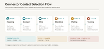
Engineers can use contact type, wire gauge, termination method, plating, operating temperature, dimensions, and lifecycle status to narrow down available rectangular connector contacts. However, housing compatibility must always be verified against the manufacturer’s specification before final selection.A reliable connector contact selection process should follow this order:
- Confirm the manufacturer, connector series, housing part number, and cavity compatibility
- Match the contact type, wire gauge, and insulation-diameter range
- Select the correct termination method and mounting context
- Verify electrical ratings and temperature-rise limits
- Evaluate contact plating and plating thickness
- Confirm the operating temperature and application environment
- Check dimensions, assembly space, and service-tool access
- Review part status, packaging format, and production requirements
1. Start with Housing, Series, and Cavity Compatibility
The connector housing is the starting point for contact selection. A contact must be designed for the exact manufacturer, connector series, housing type, and cavity configuration.Do not select a contact based only on its apparent size, pin diameter, wire range, or general description. Contacts from different connector series may look similar but differ in cavity dimensions, contact orientation, locking-lance geometry, retention-shoulder location, insertion direction, mating interface, and approved tooling.
| Compatibility Item | What to Verify |
| Manufacturer | Confirm the original connector manufacturer and approved product family |
| Connector series | Verify the exact connector series, such as Micro MATE-N-LOK or another series-specific system |
| Housing part number | Match the contact to the exact plug housing, receptacle housing, header, or other connector housing |
| Housing type | Confirm whether the housing is a plug, receptacle, header, cap, panel-mount housing, or free-hanging housing |
| Contact form | Verify whether the cavity accepts a pin contact, socket contact, plug contact, or receptacle contact |
| Cavity position | Check whether all cavities are identical or whether specific positions require different contacts |
| Contact orientation | Confirm the required barrel direction, locking-lance orientation, and insertion direction |
| Retention feature | Verify compatibility between the contact locking lance and the housing retention shoulder |
| Service tooling | Confirm the specified insertion tool and extraction tool, if required |
For example, a TE Micro MATE-N-LOK contact must be matched with the appropriate Micro MATE-N-LOK plug or receptacle housing. The contact’s locking lance must engage with the retention shoulder inside the housing cavity. A reversed contact orientation or incorrect locking-lance geometry may prevent full insertion, reduce retention force, or make future contact extraction difficult.
When reviewing a connector datasheet or application specification, identify the housing part number first, then locate the list of approved contacts for that housing. This approach is more reliable than beginning with a generic search for “pin contact,” “socket contact,” or “crimp terminal.”
After connector compatibility is confirmed in the datasheet, engineers can use Unikeyic as a sourcing reference.
2. Match the Contact Type, Wire Gauge, and Insulation Range
After confirming housing compatibility, select a contact that matches the required contact type and wire specification. The wire gauge must fall within the approved conductor range, and the actual insulation outside diameter must be compatible with the insulation barrel.| Selection Parameter | What to Verify |
| Contact type | Pin contact, socket contact, plug contact, receptacle contact, signal contact, or power contact |
| Wire gauge | Approved AWG or mm² conductor range |
| Conductor construction | Solid or stranded conductor, strand count, strand diameter, and conductor material |
| Insulation diameter | Actual outside diameter of the wire insulation |
| Insulation material | PVC, XLPE, PTFE, silicone, or another insulation material that may affect crimp behavior |
| Contact size | Contact size designation, such as Size 8, Size 12, Size 16, or Size 20, where applicable |
| Strip length | Required wire strip length from the application specification |
| Crimp dimensions | Required crimp height and crimp width for the selected wire and contact combination |
A contact designed for 22 AWG wire should not automatically be used with all 22 AWG cables. Two wires with the same AWG may have different strand constructions, insulation diameters, and insulation hardness. These differences can affect conductor crimp quality, insulation-barrel support, pull force, and long-term reliability.
For example, within a connector family such as TE Micro MATE-N-LOK, different contact variants may support different wire ranges, including 20–30 AWG, 30–26 AWG, or 24–20 AWG. The exact allowable range depends on the specific contact part number and must be verified in the applicable manufacturer documentation.
Do not force an oversized insulated wire into a smaller insulation barrel. Likewise, do not use an undersized wire in a contact designed for a larger conductor range unless the manufacturer specifically lists that combination. An improper wire-to-contact match can cause conductor strand damage, insufficient pull force, poor electrical continuity, excessive contact resistance, or wire movement after termination.
3. Choose the Appropriate Termination and Mounting Context
The contact termination method must match the connector assembly method and the final mounting context. A connector used in a free-hanging wire harness requires different contact considerations from a PCB-mounted connector, panel-mounted connector, or wire-to-board assembly.| Selection Area | Available Options | Key Considerations |
| Contact termination | Crimp, solder, IDC, PC tail, wire wrap, press-fit | Wire type, PCB requirements, approved process, tooling, production volume |
| Contact retention | Locking lance, retention clip, contact shoulder, other housing-retention features | Housing cavity design, insertion direction, extraction method, retention force |
| Connector mounting | Through-hole, SMT, panel mount, free-hanging | PCB layout, panel cutout, mechanical support, mating direction, assembly access |
| Application context | Wire-to-wire, wire-to-board, board-to-board, panel-mounted | Electrical load, serviceability, vibration, environmental exposure, cable routing |
A crimp contact is commonly used in wire-to-wire and wire-to-board connector assemblies. The wire is terminated first, and the completed contact is then inserted into the housing until the locking lance engages with the housing retention feature.
A PC-tail contact is commonly used in PCB headers and board-mounted connector assemblies. The contact tail may be installed through a plated-through hole or as a surface-mount feature, depending on the connector design. PCB thickness, finished-hole diameter, pad layout, solder process, and mechanical support requirements must be verified before selection.
Panel-mounted connectors require additional checks, including panel thickness, panel cutout dimensions, mounting hardware, cable bend radius, strain relief, and access for mating, unmating, contact insertion, and extraction.
Do not select a contact only because its termination style is correct. The contact must also match the housing, cavity, retention structure, connector mounting method, and approved assembly process.
4. Verify Electrical Ratings
Connector electrical ratings must be evaluated as a complete system. The contact rating alone does not necessarily represent the final performance of the assembled connector.| Electrical Parameter | Why It Matters |
| Rated current | Defines the allowable current under specified test conditions |
| Wire gauge | Affects current-carrying capability, voltage drop, and temperature rise |
| Rated voltage | Defines the maximum operating voltage under specified insulation and spacing conditions |
| Contact resistance | Affects voltage drop, power loss, and heat generation at the mating interface |
| Termination resistance | Indicates resistance introduced by the wire-to-contact termination |
| Temperature rise | Shows thermal performance when current flows through the connector system |
| Insulation resistance | Indicates the ability of insulating materials to resist leakage current |
| Dielectric withstanding voltage | Indicates the system’s ability to withstand a specified voltage without breakdown |
Current rating must be checked together with wire gauge, ambient temperature, energized circuit count, contact resistance, housing material, airflow, and derating conditions. A power contact rated for a specified current under one test condition may require derating in a tightly packed housing, high-temperature enclosure, or application with multiple adjacent energized circuits.
For example, a connector series may specify a rated voltage, current rating, maximum temperature rise, insulation resistance, dielectric-withstanding voltage, and maximum termination resistance. These values should be taken from the product specification for the complete connector system, not assumed from a distributor filter or a generic contact description.
When the application involves continuous power, high inrush current, motors, heaters, battery connections, or high ambient temperature, review the manufacturer’s derating curve and temperature-rise data. Verify that the selected contact, wire, housing, and mating connector remain within their allowed operating limits under worst-case conditions.
5. Evaluate Contact Plating and Plating Thickness
Contact plating affects electrical performance, corrosion resistance, mating durability, and long-term connector reliability. Common contact plating materials include gold, tin, silver, and manufacturer-specific plating systems.| Plating Type | Typical Characteristics | Common Considerations |
| Gold plating | Excellent corrosion resistance and stable low-level signal performance | Often used for low-current signals, frequent mating cycles, harsh environments, and applications requiring stable contact resistance |
| Tin plating | Cost-effective and widely used in general-purpose connector systems | Suitable for many commercial and industrial applications; fretting corrosion, mating cycles, and environmental conditions must be evaluated |
| Silver plating | High electrical conductivity and good performance in some high-current applications | May require consideration of tarnishing, environmental exposure, and application-specific mating requirements |
| Manufacturer-specific plating | May include selective plating, nickel underplating, or specialized alloy systems | Verify the exact plating stack, thickness, mating-area coverage, and approved application conditions |
When evaluating plating, review more than the visible finish color. The manufacturer’s datasheet may specify the base material, underplating, plating material, plating thickness, mating-area coverage, and termination-area finish.
For example, a gold-plated contact may use selective gold plating only on the mating area, while the termination area may use tin plating or another finish compatible with crimping or soldering. A nickel underplate may be used between the base material and gold layer to improve durability, diffusion resistance, or corrosion performance.
Plating thickness is commonly specified in micrometers (µm) or microinches (µin). Do not assume that two gold-plated contacts have the same mating performance simply because both are described as “gold plated.” The plating thickness, plating area, underplating, base material, mating force, environmental conditions, and number of mating cycles can all affect reliability.
Gold plating is often preferred for low-level signal applications, low-voltage circuits, high-reliability interconnects, and environments where oxidation resistance is critical. Tin plating is commonly used for cost-sensitive commercial and industrial applications, particularly where the connector has adequate contact force and is not subject to severe fretting conditions.
The final plating selection should consider:
- Required mating-cycle life
- Signal level and current level
- Corrosion exposure, humidity, and contamination
- Vibration and potential fretting corrosion
- Operating temperature
- Mating-contact plating compatibility
- Contact resistance requirements
- Cost and availability
- Manufacturer-approved use conditions
6. Check Operating Temperature and Application Environment
The operating temperature of a connector contact must be evaluated together with the housing material, wire insulation, current load, contact resistance, and actual installation environment. The connector assembly is limited by its lowest-rated component.A contact may be specified for a broad temperature range, but the connector housing, wire insulation, seals, grommets, PCB material, or adjacent components may have lower temperature limits. Always verify the operating-temperature range for the complete connector system.
Environmental conditions that can affect connector-contact selection include:
- High or low ambient temperature
- Temperature cycling and thermal shock
- Vibration and mechanical shock
- Humidity, condensation, and water exposure
- Salt spray, corrosive gases, oils, fuels, and chemicals
- Dust, particles, and industrial contaminants
- UV exposure for outdoor applications
- Repeated mating and unmating
- Continuous current loading and resulting temperature rise
When evaluating the operating environment, consider the full assembly rather than the contact alone. This includes the connector housing, mating connector, wire insulation, strain relief, seals, backshells, cable routing, enclosure protection level, and mounting method.
7. Verify Dimensions and Available Assembly Space
Physical dimensions are critical when selecting connector contacts, especially in compact equipment, high-density PCB assemblies, panel-mounted systems, and wire harnesses with limited routing space.Verify the dimensions of the contact, housing, cavity, PCB interface, and final assembly location before releasing the design or purchasing production quantities.
| Dimensional Area | What to Verify |
| Contact dimensions | Length, width, height, mating length, barrel size, and retention-feature geometry |
| Housing cavity | Cavity width, height, depth, pitch, insertion direction, and retention-shoulder position |
| Wire and strain relief | Wire outside diameter, bend radius, insulation-barrel clearance, and cable-routing space |
| PCB interface | PCB thickness, finished-hole size, pad layout, tail length, and component keep-out area |
| Panel interface | Panel cutout, panel thickness, mounting clearance, latching access, and mating clearance |
| Service access | Space for crimp tools, insertion tools, extraction tools, inspection, repair, and rework |
The contact drawing, housing drawing, connector assembly drawing, and application drawing should be reviewed together. A contact may be electrically compatible but still create assembly problems if there is insufficient clearance for the wire bend radius, crimp tool, contact insertion tool, extraction tool, or connector mating operation.
For PCB-mounted connectors, verify the PCB footprint, plated-through-hole dimensions, solder-tail or PC-tail length, board thickness, and nearby-component clearance. For panel-mounted connectors, confirm the panel cutout, mounting orientation, cable exit direction, and access for mating and unmating.
8. Check Part Status and Packaging Format
Before finalizing a connector contact, verify its product lifecycle status and available packaging format. A technically correct contact may still create production or supply-chain risk if it is not recommended for new designs, approaching last-time-buy status, or unavailable in the required packaging format.| Part Status | Meaning |
| Active | Available for current production and generally suitable for new designs |
| New | Recently introduced product; verify qualification status, availability, and long-term supply plans |
| Not Recommended for New Design (NRND) | Existing product may remain available, but it is not recommended for new product development |
| Last Time Buy | Manufacturer has announced a final opportunity to place orders before discontinuation |
| Obsolete | No longer manufactured or supported by the original manufacturer |
Packaging and supply format may include:
- Tape-and-reel contacts
- Strip-form contacts
- Loose-piece contacts
- Bags
- Trays
- Tubes
- Bulk packaging
Packaging format must match the production method. For example, a reel contact may be required for automated crimping, while a loose-piece contact may be more practical for field repair or low-volume assembly. The manufacturer part number, packaging suffix, minimum order quantity (MOQ), standard pack quantity (SPQ), and lead time should be confirmed before releasing the bill of materials.
Series-Specific Example: Why Manufacturer Specifications Matter
TE Micro MATE-N-LOK is an example of a rectangular connector system in which contact selection depends on the exact housing, contact configuration, wire range, termination requirements, and assembly process.| Parameter | Representative Selection Requirement |
| Housing compatibility | Match plug and receptacle contacts to the corresponding approved housing |
| Representative wire range | 20–30 AWG, depending on the specific contact part number |
| Rated voltage | 250 V AC/DC, subject to the applicable product specification and use conditions |
| Operating temperature | -40°C to +105°C, subject to the applicable product specification |
| Maximum termination resistance | 20 mΩ, subject to the applicable product specification |
| Contact orientation | Match the required contact orientation to the housing cavity and insertion direction |
| Contact retention | Confirm that the locking lance engages correctly with the housing retention shoulder |
| Crimp requirements | Follow the specified wire strip length, crimp height, crimp width, tooling, and inspection requirements |
| Service requirements | Use the approved insertion and extraction tools where required |
The values above are representative system-level references and must not be used as a substitute for the current manufacturer documentation. Contact part numbers within the same connector series may have different wire ranges, plating options, packaging formats, and approved tooling.
For any production design, confirm the exact contact part number, housing part number, wire specification, crimp tooling, application specification, and product specification before purchase and assembly.
Crimping and Assembly Considerations
Correct contact selection is only the first step. Connector reliability also depends on wire preparation, crimp quality, contact insertion, housing retention, and use of the specified assembly tools.A contact that is compatible with the housing and wire may still fail in service if the crimp dimensions, conductor position, locking-lance orientation, or insertion process do not meet the manufacturer’s application specification.
Verify the Wire Strip Length and Conductor Condition
The wire strip length must match the value specified for the selected contact and wire size. An incorrect strip length can reduce crimp quality, damage strands, expose excessive conductor, or interfere with contact insertion.Before crimping, verify the following:
- The wire gauge matches the selected contact’s approved AWG or mm² range
- The wire insulation outside diameter is compatible with the insulation barrel
- The wire strip length meets the application specification
- The stripped conductor is clean, straight, and free from oxidation, contamination, damaged strands, or nicked strands
- The conductor strands are fully inserted into the wire barrel
- The wire insulation is positioned correctly within the insulation barrel
- No conductor strands extend excessively beyond the wire barrel
- No insulation is trapped inside the conductor-crimp area unless specifically permitted by the manufacturer
Inspect the Wire Barrel Crimp
The wire barrel creates the mechanical and electrical connection between the contact and the stripped conductor. A correct crimp compresses the conductor strands to the required geometry without cutting, excessively flattening, or improperly deforming the wire.Inspect the wire barrel crimp for the following conditions:
- The conductor is fully seated in the wire barrel
- The crimp profile matches the required F-crimp, O-crimp, or manufacturer-specific geometry
- The crimp height meets the specified value and tolerance
- The crimp width meets the specified value, where applicable
- The bellmouth is present and within the acceptable condition
- No conductor strands are cut, severely deformed, or pushed out of the barrel
- No insulation is crimped into the conductor barrel unless specified
- The cutoff tab does not interfere with housing insertion, mating, or adjacent contacts
Crimp width must also be evaluated where required. The correct width helps ensure that the wire barrel is properly formed around the conductor without excessive spreading, sharp edges, or interference with the housing cavity.
Check the Insulation Barrel Crimp
The insulation barrel provides mechanical support and strain relief. It should retain the insulated wire without cutting, crushing, or excessively deforming the insulation.The insulation barrel does not normally provide the primary electrical connection. Its function is to reduce stress transfer from the cable to the conductor crimp during handling, vibration, bending, and service.
Verify the following:
- The insulation barrel is positioned over the insulated portion of the wire
- The insulation barrel does not extend into the conductor-crimp area
- The crimp supports the insulation without cutting or piercing it
- The insulation is not excessively flattened, split, or damaged
- The wire is held securely but can tolerate the manufacturer-defined flex condition
- The contact remains straight after crimping
- The pin, socket, spring member, locking lance, and other functional features are not bent or damaged
Verify Crimp Height, Crimp Width, and Bellmouth
Crimp dimensions must be verified using the approved inspection method. The required dimensions vary by contact part number, wire gauge, wire construction, insulation diameter, and crimp-tool configuration.
| Inspection Item | Purpose |
| Crimp height | Controls conductor compression and affects electrical resistance, pull force, and long-term reliability |
| Crimp width | Confirms the wire barrel has formed to the intended profile |
| Bellmouth | Helps prevent conductor damage at the barrel entrance and confirms correct crimp-tool setup |
| Conductor brush | Indicates that conductor strands extend appropriately beyond the wire barrel, where permitted |
| Cutoff tab | Must not interfere with housing insertion, contact retention, or mating performance |
| Wire position | Confirms that the conductor and insulation are located correctly in their respective crimp areas |
A properly formed bellmouth is a small flare at the entrance and exit of the wire barrel. It helps prevent sharp barrel edges from cutting or damaging the conductor strands. Excessive bellmouth may reduce effective conductor support, while insufficient bellmouth may increase the risk of strand damage.
Do not judge crimp quality by appearance alone. Visual inspection should be combined with crimp-height measurement, pull-force testing, electrical testing, and any additional verification specified by the manufacturer.
Confirm Conductor Position and Contact Straightness
After crimping, confirm that the conductor, insulation, and contact body remain aligned. An incorrectly positioned wire can affect contact insertion, housing retention, mating alignment, and electrical performance.
Check that:
- The conductor is centered in the wire barrel
- The insulation is positioned correctly under the insulation barrel
- The contact is not twisted, bent, or laterally deformed
- The mating end of the pin or socket remains undamaged
- Socket spring members are not collapsed, spread, or distorted
- The locking lance is not bent, flattened, or damaged
- The contact orientation feature remains intact
- The cutoff tab does not obstruct insertion into the housing cavity
Verify Contact Insertion and Housing Retention
After crimping, insert the contact into the correct housing cavity in the specified direction. The locking lance, retention clip, or other retention feature must engage fully with the housing retention shoulder.
A correctly inserted contact should reach its fully seated position without requiring excessive force. After insertion, perform a light pull-back check from the wire side when permitted by the assembly procedure. The contact should not back out of the cavity.
Verify the following:
- The contact is inserted into the correct cavity position
- The contact orientation matches the housing cavity design
- The locking lance engages the housing retention shoulder
- The contact is fully seated at the required depth
- The contact does not back out during a retention check
- The mating end is aligned correctly within the housing
- The wire exits the housing in the intended direction
- No housing damage, cavity deformation, or locking-lance damage occurs during insertion
Use the Correct Crimp, Insertion, and Extraction Tools
Connector contacts must be assembled using the tooling approved for the specific contact part number, wire gauge, and packaging format. Using a generic crimp tool may produce a visually acceptable crimp that does not meet the required crimp height, width, pull force, or bellmouth condition.
| Tool Type | What to Verify |
| Crimp tool | Approved for the specific contact part number and wire gauge |
| Die set | Matches the required crimp geometry and contact size |
| Applicator | Matches reel or strip-form contact packaging and approved production equipment |
| Insertion tool | Compatible with the contact, housing cavity, and retention design |
| Extraction tool | Designed to release the locking lance or retention feature without damaging the housing or contact |
Loose-piece contacts may require a hand crimp tool or bench crimper, while reel contacts generally require a compatible applicator. The applicator must be set up and validated for the specified contact and wire combination before production begins.
Use an approved insertion tool when the contact is too small, recessed, or sensitive to be inserted reliably by hand. Use the specified extraction tool when removing a contact from a housing; do not pull on the wire or force the contact out with an improvised tool.
Crimp and Assembly Quality Checklist
| Inspection Area | Verification Requirement |
| Wire gauge | Matches the approved contact wire range |
| Wire strip length | Meets the application specification |
| Conductor condition | Strands are clean, undamaged, and fully inserted |
| Wire barrel crimp | Crimp height, crimp width, and profile meet specification |
| Insulation barrel crimp | Provides support without damaging insulation |
| Bellmouth | Present and within the allowable condition |
| Conductor position | Correctly located in the wire barrel |
| Contact alignment | Contact remains straight and mating features are undamaged |
| Locking lance | Undamaged and correctly oriented |
| Housing retention | Contact is fully seated and retained in the cavity |
| Tooling | Approved crimp tool, die set, applicator, insertion tool, and extraction tool are used |
A complete crimp-validation process may also include pull-force testing, crimp microsection analysis, electrical-resistance testing, contact-retention testing, and visual inspection according to the connector manufacturer’s application specification.
Common Connector Contact Selection Mistakes
Many connector failures result from incomplete compatibility checks rather than from an obvious product defect. The following mistakes can lead to poor retention, high contact resistance, overheating, assembly defects, mating problems, and field failures.1. Selecting the Contact Before Confirming the Housing
Do not begin with a generic search for a pin, socket, crimp terminal, or contact based only on appearance. The housing part number, connector series, cavity design, and retention structure must be confirmed first.
A contact that looks physically similar may still be incompatible because of differences in:
- Contact cavity dimensions
- Locking-lance geometry
- Retention-shoulder position
- Contact orientation
- Insertion direction
- Mating interface
- Plug or receptacle configuration
- Approved insertion and extraction tools
2. Confusing Pin, Socket, Male, Female, Plug, and Receptacle Terms
Pin and socket describe the mating interface, while plug and receptacle often describe the connector housing or assembly role. These terms must not be treated as automatic equivalents.
For example, a plug housing in one connector series may use socket contacts, while a plug housing in another series may use pin contacts. Likewise, a “male” or “female” description used by a distributor may not fully identify the required contact configuration.
Verify the following before selection:
- Pin contact or socket contact
- Plug contact or receptacle contact
- Compatible housing type
- Mating connector configuration
- Contact orientation
- Manufacturer contact drawing
- Product specification and application specification
A contact may enter a housing cavity but still fail to lock correctly. Proper fit requires the locking lance, retention clip, contact shoulder, and cavity retention feature to engage as designed.
An incorrect contact may cause:
- Partial insertion
- Contact back-out during wire pulling or mating
- Damage to the locking lance
- Low retention force
- Incorrect mating depth
- Interference with adjacent cavities
- Difficult or impossible extraction
4. Matching Only the AWG and Ignoring Insulation Diameter
Wire gauge alone is not enough to select a crimp contact. Two wires with the same AWG can have different conductor constructions, strand counts, insulation materials, and insulation outside diameters.
| Wire Parameter | Why It Matters |
| Wire gauge | Determines whether the conductor fits the approved wire-barrel range |
| Conductor construction | Affects crimp compression, pull force, flexibility, and strand damage risk |
| Insulation diameter | Determines whether the insulation barrel can provide proper support |
| Insulation material | Influences crimp deformation and resistance to cutting or cold flow |
| Strip length | Affects conductor location and the quality of both conductor and insulation crimps |
| Crimp height | Controls conductor compression and electrical/mechanical performance |
| Contact size | Must match the wire barrel, insulation barrel, and housing cavity |
Do not use a contact designed for one 22 AWG wire with another 22 AWG wire without checking the insulation diameter and approved wire specification. An oversized insulation diameter can damage the insulation barrel or prevent proper crimp formation, while an undersized insulation diameter can result in poor strain relief.
5. Selecting the Correct Contact but the Wrong Termination or Mounting Type
The termination type must match the complete connector assembly and installation method. A crimp contact, solder contact, IDC contact, PC-tail contact, and press-fit contact are not interchangeable unless the manufacturer explicitly approves them for the same connector system.
| Selection Area | Typical Options | Key Verification |
| Contact termination | Crimp, solder, IDC, PC tail, wire wrap, press-fit | Approved process, wire or PCB compatibility, tooling |
| Contact retention | Locking lance, retention clip, shoulder, cavity latch | Housing cavity and insertion direction |
| Connector mounting | Through-hole, SMT, panel mount, free-hanging | PCB layout, panel design, mechanical support |
| Application type | Wire-to-wire, wire-to-board, board-to-board, panel mount | Electrical load, access, serviceability, environment |
For example, a panel-mounted connector housing may use crimp contacts, but the panel cutout, mounting orientation, cable exit direction, and mating clearance still need to be validated. Similarly, a PCB header may use PC-tail contacts, but the PCB finished-hole size, board thickness, and soldering process must match the product specification.
6. Choosing Plating Based Only on Cost or Appearance
Gold, tin, and silver plating serve different performance requirements. A contact should not be selected only because it is lower cost or because its finish appears similar to another contact.
Verify the complete plating system, including:
- Base material
- Underplating
- Mating-area plating
- Termination-area plating
- Localized or overall plating coverage
- Plating thickness in µm or µin
- Required mating-cycle life
- Corrosion and humidity exposure
- Vibration and fretting-corrosion risk
- Mating-contact finish compatibility
7. Using Rated Current Without Checking Temperature Rise
A contact current rating must never be evaluated in isolation. Actual temperature rise depends on conductor size, contact resistance, termination resistance, housing material, energized-circuit count, airflow, ambient temperature, and application duty cycle.
For power contacts, confirm:
- Rated current under the stated test conditions
- Wire gauge and conductor temperature rating
- Contact resistance and termination resistance
- Temperature-rise limits
- Derating curves
- Adjacent energized positions
- Ambient temperature
- Continuous-load versus intermittent-load conditions
8. Using an Unapproved Crimp Tool or Applicator
A generic crimp tool can create a termination that looks acceptable but does not meet the specified crimp height, crimp width, bellmouth, pull force, or conductor-compression requirements.
The approved tool system should match:
- Contact part number
- Wire gauge
- Wire insulation diameter
- Contact packaging format
- Crimp-tool model
- Die set
- Applicator, where reel or strip-form contacts are used
- Required crimp height and width
9. Ignoring Operating Temperature and Environmental Exposure
A connector contact may be compatible electrically and mechanically but still fail if the application environment exceeds the rated limits of the connector system.
Evaluate:
- Operating-temperature range
- Current-generated temperature rise
- Vibration and mechanical shock
- Humidity and condensation
- Water ingress and washdown exposure
- Corrosive gases, oils, fuels, chemicals, and salt spray
- Dust and industrial contaminants
- UV exposure
- Required mating and unmating cycles
10. Ignoring Part Status, Packaging, and Supply Format
A technically correct contact can still create a production problem if it is obsolete, NRND, available only in an unsuitable packaging format, or subject to unacceptable lead times and order quantities.
Before approving a connector contact for production, verify:
| Supply Item | What to Check |
| Part status | Active, New, NRND, Last Time Buy, or Obsolete |
| Packaging format | Loose piece, strip form, tape and reel, tray, tube, bag, or bulk |
| Production method | Manual crimping, semi-automatic crimping, automatic crimping, field repair |
| Tooling compatibility | Hand tool, die set, applicator, insertion tool, extraction tool |
| Commercial availability | Stock level, MOQ, SPQ, lead time, and approved source |
| Documentation | Current datasheet, product specification, application specification, and PCN status |
For automated crimping, confirm that the selected part number is available in the correct reel or strip format and that a compatible applicator is available. For prototype, maintenance, or field repair work, loose-piece contacts may be more practical.
Connector Contact Selection Checklist
Use this checklist before finalizing a connector contact for design, procurement, prototype assembly, or production release.| Verification Category | Key Items to Confirm | Recommended Documentation |
| Connector system | Manufacturer, connector series, housing part number, cavity position | Product specification, housing drawing, customer drawing |
| Contact compatibility | Pin/socket type, plug/receptacle configuration, contact orientation, locking lance, retention structure | Contact drawing, application specification |
| Wire compatibility | AWG or mm² range, conductor construction, insulation diameter, strip length | Application specification, wire datasheet |
| Termination | Crimp, solder, IDC, PC tail, wire wrap, press-fit | Application specification, termination drawing |
| Electrical performance | Rated current, rated voltage, contact resistance, termination resistance, temperature rise | Product specification, derating data |
| Plating | Gold, tin, silver, underplating, mating-area coverage, plating thickness | Contact datasheet, plating specification |
| Environment | Operating temperature, humidity, vibration, shock, corrosion, mating cycles | Product specification, qualification report |
| Dimensions | Contact dimensions, housing cavity, PCB interface, panel cutout, assembly clearance | Contact drawing, housing drawing, PCB drawing |
| Mounting context | Wire-to-wire, wire-to-board, PCB mount, panel mount, free-hanging | Assembly drawing, application specification |
| Tooling | Crimp tool, die set, applicator, insertion tool, extraction tool | Tooling documentation, application specification |
| Lifecycle | Active, NRND, last-time-buy, obsolete status | Manufacturer lifecycle notice, PCN |
| Packaging and supply | Loose piece, strip form, tape and reel, MOQ, SPQ, lead time | Distributor data, manufacturer packaging information |
Compatibility Verification
Confirm the manufacturer, connector series, housing part number, cavity position, contact form, and retention structure before selecting a contact. The contact must be approved for the specific housing and must match the intended pin, socket, plug, or receptacle configuration.
Verify the contact orientation, locking-lance geometry, housing retention shoulder, insertion direction, and required service tools. This is particularly important for connector systems with different plug and receptacle contact orientations.
Wire and Termination Verification
Confirm that the wire gauge, conductor construction, insulation diameter, strip length, and crimp dimensions match the selected contact. The wire barrel and insulation barrel must both support the actual wire specification.
For crimp contacts, use the specified crimp tool, die set, or applicator. For solder, IDC, PC-tail, or press-fit contacts, confirm the manufacturer-approved termination process and installation requirements.
Electrical and Environmental Verification
Verify the rated current, rated voltage, contact resistance, termination resistance, insulation resistance, dielectric-withstanding voltage, and temperature-rise limits for the complete connector system.
Evaluate operating temperature, vibration, mechanical shock, humidity, corrosion exposure, contamination, and mating-cycle requirements. The actual connector rating is limited by the lowest-rated component in the completed assembly.
Plating and Dimensions Verification
Confirm the plating material, base material, underplating, mating-area coverage, termination-area finish, and plating thickness. Select gold, tin, silver, or another approved plating system based on the electrical, environmental, and mating-cycle requirements.
Review contact dimensions, housing cavity dimensions, PCB interface dimensions, panel cutout requirements, wire-routing space, and access for insertion, extraction, inspection, repair, and rework.
Production and Supply Verification
Confirm that the contact is active and available in a packaging format suitable for the intended production method. Verify the required crimp tool, die set, applicator, insertion tool, and extraction tool before releasing production documentation.
Review MOQ, SPQ, stock availability, lead time, manufacturer packaging suffixes, and lifecycle notices. These checks help prevent a technically correct design from becoming difficult to build, service, or source.
When a BOM includes multiple connector families, procurement teams can use Unikeyic to centralize manufacturer part number review, datasheet checks, lifecycle status confirmation, stock availability review, and RFQ requests. Unikeyic is an electronic components distribution brand operated by UNIKEY ELECTRONICS PTE. LTD., serving design engineers, buyers, EMS providers, ODMs, and OEMs through unikeyic.com, with broad in-stock component availability and support for global sourcing workflows.
Final Selection Rule
Select a connector contact only after verifying three areas:
- Compatibility verification: The contact matches the manufacturer, connector series, housing part number, cavity design, contact orientation, retention structure, and required pin, socket, plug, or receptacle configuration.
- Performance verification: The selected contact meets the wire-gauge range, insulation-diameter range, termination method, electrical ratings, plating requirements, operating-temperature range, and environmental conditions.
- Production verification: The required crimp tool, die set, applicator, insertion tool, extraction tool, packaging format, lifecycle status, and supply conditions are suitable for the intended production or service process.
Frequently Asked Questions
Are Connector Contacts and Terminals the Same?Connector contacts and terminals are related terms, but they are not always identical. A connector contact is typically the conductive component installed in a connector housing and designed to mate with another contact, such as a pin contact or socket contact.
A terminal is a broader term that may describe a conductive component used to terminate a wire, PCB trace, stud, busbar, or connector interface. Examples include ring terminals, spade terminals, PCB terminals, crimp terminals, and connector terminals.
In connector datasheets, the manufacturer may use “contact,” “terminal,” “pin,” “socket,” “plug contact,” or “receptacle contact” to identify the part. Always use the terminology and part-number definitions stated in the relevant datasheet and application specification.
What Is the Difference Between Pin and Socket Contacts?
A pin contact has a projecting mating section that inserts into a corresponding socket contact. A socket contact has a receptacle-style mating section that receives the pin and provides the required contact force.
| Contact Type | Mating Structure | Typical Role |
| Pin contact | Protruding male-style mating end | Mates by entering a socket contact |
| Socket contact | Receptacle-style mating end with spring members | Mates by receiving and retaining a pin contact |
However, pin and socket should not automatically be equated with plug and receptacle. Depending on the connector series, a plug housing may use pin contacts or socket contacts. Confirm the required configuration using the connector housing part number, contact drawing, and manufacturer documentation.
How Do I Match a Contact to a Connector Housing?
Start with the connector manufacturer, connector series, and exact housing part number. Then identify the approved contact part numbers listed for that housing.
Verify the following before ordering or assembling contacts:
- Housing type: plug, receptacle, header, cap, panel-mount housing, or other configuration
- Contact form: pin, socket, plug contact, or receptacle contact
- Wire range: approved AWG or mm² range
- Insulation diameter: compatible with the insulation barrel
- Cavity design: contact orientation, insertion direction, and cavity position
- Retention system: locking lance, retention clip, or retention shoulder
- Tooling: approved crimp, insertion, and extraction tools
- Documentation: product specification, application specification, customer drawing, and contact drawing
Is Crimping Better Than Soldering?
Neither method is universally better. The correct choice depends on the connector design, production volume, wire type, tooling availability, operating environment, and manufacturer-approved process.
| Factor | Crimp Termination | Solder Termination |
| Best suited for | Production wire harnesses, wire-to-wire assemblies, and repeatable high-volume manufacturing | Solder-cup contacts, PCB-mounted interfaces, field installation, repair, and specialized low-volume work |
| Primary process control | Crimp height, crimp width, bellmouth, conductor position, pull force, and approved tooling | Solder wetting, solder coverage, heat control, solder wicking, strain relief, and inspection |
| Mechanical support | Insulation barrel typically provides integrated strain relief | Separate strain-relief design may be needed because solder joints should not carry repeated flex stress |
| Automation | Highly suitable for reel contacts and applicator-based processing | Possible, but more sensitive to heat, flux, dwell time, and cleaning control |
Crimping is generally preferred for production harnesses when the approved contact, wire, crimp tool, and process controls are used. Soldering is appropriate only when the contact and connector system are specifically designed and qualified for solder termination.
How Do I Choose Between Gold- and Tin-Plated Contacts?
Choose plating based on the electrical signal level, current load, required mating cycles, vibration exposure, corrosion risk, operating temperature, and mating-contact finish.
| Plating Option | Usually Preferred When | Key Considerations |
| Gold plating | Low-level signal circuits, corrosion-sensitive environments, frequent mating, and stable low-resistance requirements | Verify gold thickness, nickel underplating, selective-plating area, mating-cycle rating, and cost |
| Tin plating | General-purpose commercial and industrial connections with appropriate contact force and controlled environmental conditions | Evaluate fretting corrosion, vibration, humidity, mating cycles, and contact-resistance requirements |
| Silver plating | Certain high-current applications where conductivity is important | Evaluate tarnishing behavior, environmental exposure, and the mating-contact system |
Do not select a contact simply because it is described as gold-plated or tin-plated. Confirm the base material, underplating, plating thickness, mating-area coverage, termination-area finish, and environmental qualification requirements stated by the manufacturer.
Conclusion
Selecting the right connector contact requires a system-level review of the connector housing, connector series, cavity design, pin or socket configuration, wire gauge, insulation diameter, termination method, plating, electrical ratings, operating environment, dimensions, tooling, lifecycle status, and packaging format.The most reliable selection approach is to begin with housing compatibility, then verify wire and termination requirements, electrical and environmental performance, plating and physical dimensions, and finally the tooling and supply conditions required for production. Always validate the final combination against the manufacturer’s product specification, application specification, contact drawing, housing drawing, and current lifecycle documentation.


