Led flikers?

24Volts

Mar 21, 2010
164
Joined
Mar 21, 2010
Messages
164
Hello,

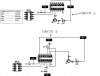
I am designing a small board where it requires several power supplies. they are 3.3VDC, 5VDC and later perhaps 12VDC. In this board, I am trying to design a small circuit which detects if any of these voltages are missing on the board. If all the voltages are available a green led will light up. If any of these voltages are missing, the led will not light up. At the same time, the green led can be used as a flasher by a signal coming from an MCU.

I designed the circuit and it works. However, when I went and add a relay with the same powers used on the board, the green led sinks in luminosity when the relay is turned on by a switch. I never understood why this phenomenon happens and moreover how do we get rid of it?

I have provided the schematic in the attachment below. I am stuck on this and don't know what component needs to be modified in my circuit. If anyone has a suggestion, it would be very appreciated!

Thanks all in advance.
 

Attachments

  • FlickerCircuit.jpg
    FlickerCircuit.jpg
    70.6 KB · Views: 97
Last edited:

Harald Kapp

Moderator
Moderator
Nov 17, 2011
14,272
Joined
Nov 17, 2011
Messages
14,272
Your circuit seems to be more complicated than necessary: You can drive T1 via R2 directly from pin 7 of the MCU, no need for the AND gate.
You should then connect the emitter of T1 directly to GND, put the LED and R3 in the collector circuit (from collector of T1 to VFF). This wil ensure that T1 is either on or off completely.In your circuit, the voltage drop across the LED and across R3 tends to turn off the transistor even if it is supposed to be on.

Check VFF. What happens when you turn on the relay? does VFF stay stable, or does it go down? This would be a sign of the power supply being overloaded by the relay.
 

24Volts

Mar 21, 2010
164
Joined
Mar 21, 2010
Messages
164
Hi Harald Kapp,

I don't know why I put the Led and resistor at the emitter side of T1?? I always get lured into using the emitter bias configuration figuring that it will stabilize my circuit a little better. But you did solve the problem and I thank you very much. I relocated the led and the resistor at the collector side as you said and no more flicker or dimming of the led when the relay goes on. View circuit #1 in attachment.

The reason I need the AND gate is because the led is not just for power indication. Its also as a power indicator which monitors if any of the voltages are missing on the board. Suppose we have a board with 3.3VDC, 5.0Vdc, 9VDC and 12VDC. If there is any of those voltages missing, then the led should be off. Only and only when all the voltages are present can the led be on. On top of that the led requires blinking from an MCU signal. You can view the same circuit but with 3.3VDC, 5.0Vdc, 9VDC and 12VDC voltages being monitored by the AND gate at circuit #2.

I don't know of any other way to do this, so for now it works and some day when I get a better idea I will upgrade :)

Thanks for your help
24v
 

Attachments

  • Flikker2.png
    Flikker2.png
    25.6 KB · Views: 176

KrisBlueNZ

Sadly passed away in 2015
Nov 28, 2011
8,393
Joined
Nov 28, 2011
Messages
8,393
You can monitor two or three supply voltages using a supply voltage monitor IC. Many of these are designed to generate a reset signal for a microprocessor and also include a power good delay which causes the micro to be held reset until the supply voltages have been stable for a certain amount of time, usually between 50 and 500 milliseconds. This will mean that when all the voltages are within specification, you won't know about it until a short time afterwards. Whether this is a good thing or a bad thing in your application, I don't know.

Some of these supervisors also have fixed threshold voltages, i.e. fixed voltage tolerances for each rail voltage. With some of them, voltage thresholds are determined by external resistors connected as a voltage divider, so you can vary the threshold voltages for these.

Many of them also have a watchdog function - a pin on the device must be toggled by the micro, to tell the device that the firmware is still running; if pulses stop, the device resets the micro. In some of them, this function can be disabled if it's not used. If it can't be disabled, and your circuit doesn't have a micro, perhaps the circuit already has some kind of alternating signal that could be fed into the watchdog pin.

Digikey have a category for these components: Product Index > Integrated Circuits (ICs) > PMIC - Supervisors. Go to http://www.digikey.com/product-sear...25,9140002,9140003,9140004&stock=1&quantity=1 and you'll find over 700 devices (including variants of devices) that could be suitable. You can narrow down the options by selecting through-hole packages only, or eliminating packages with no leads at all (which are difficult to hand-solder).

The Texas Instruments TPS3510 (http://www.digikey.com/product-detail/en/TPS3510P/296-3318-5-ND/372347) monitors a 12V rail for overvoltage, and a 5V rail and a 3.3V rail for undervoltage and overvoltage, and could be suitable. Digikey's price is USD 1.20 in one-off quantity. The Texas Instruments TPS3514 (http://www.digikey.com/product-detail/en/TPS3514N/296-34603-5-ND/1671434) is similar but with some extra features. These are the best cheap through-hole options I could find, but there are LOTS more options in SMT packages.
 

24Volts

Mar 21, 2010
164
Joined
Mar 21, 2010
Messages
164
Hi KrisBlueNZ,
wow, I didn't even know these things existed LOL

I have seen one that pretty much does what I need for now, its theTPS3510P at

http://www.ti.com/lit/ds/symlink/tps3510.pdf

I have a question.

-According to the spec, the PGO pin is specked at 10 ma sinking current. Does this mean if I want to drive a led of 25 ma, I need a transistor at the output?

Thanks for your help!
 

KrisBlueNZ

Sadly passed away in 2015
Nov 28, 2011
8,393
Joined
Nov 28, 2011
Messages
8,393
Are you talking about the PGO (power good output) pin? It's an open drain output, which means it pulls low but needs an external pullup resistor to pull it high when power is good. So you need a pullup AND a buffer. Your simplest option would be:

R1: 10k resistor
R2: 220 ohm resistor (adjust value to determine LED brightness)
Q1: General purpose NPN transistor e.g. 2N3904, BC547B
LED1: Your LED.

Circuit node 1: TPS3510 pin 8 ("PGO"); R1 terminal 2; Q1 base.
Circuit node 2: Q1 emitter; R2 terminal 1.
Circuit node 3: R2 terminal 2; LED1 anode.
VCC: connect Q1 collector.
0V: connect LED1 cathode.

In other words, PGO needs a 10k pullup to VCC (5V) and feeds the base of an NPN whose collector is tied to VCC; its emitter drives the LED through the series resistor.
 

24Volts

Mar 21, 2010
164
Joined
Mar 21, 2010
Messages
164
Hello KrisBlueNZ,

First, I would sincerely like to thank you for your effort in helping me this way, its so nice of you !

Okay I understand.

I was also wondering though, I wouldn't need the NPN transistor (as you mentioned -Q1) if my load at PGO would be less than 10 ma... right?

Just want to confirm that I am reading this right since the spec sheet says:

Output sink current I/O, sink >>> PGO = 10 ma

thanks again!
 

KrisBlueNZ

Sadly passed away in 2015
Nov 28, 2011
8,393
Joined
Nov 28, 2011
Messages
8,393
Yes, you could connect the LED between PGO and 0V, and use a lower pullup resistor value, as long as the current into PGO is less than 10 mA. For example if VCC is 5V, the resistor must be at least 500 ohms. Say you use 560 ohms.

When any power rail is outside specification, i.e. "power is not good", the IC will pull PGO low, and the LED will turn OFF because there will be no voltage across it. When power is good, the chip will stop sinking current through PGO, and the current flow through the resistor will now supply the LED. If your LED is green and has a forward voltage of 2.5V, for example, the LED current will be I = V / R = (5 - 2.5) / 560 = 4.5 mA. A high-efficiency, low-current LED will give you good brightness at 4.5 mA.

Edit: If it's possible that VCC might be more than 5V, you'll need to increase the resistor value accordingly. If VCC may vary over a wide range, you can drive the LED with a current sink; let me know and I'll draw up a circuit.
 

24Volts

Mar 21, 2010
164
Joined
Mar 21, 2010
Messages
164
Hi KrisBlueNZ,

Thanks for your help.... for I have taken already too much of your time.... I think I can take it from here...

Thanks for your time/help !
Very appreciated....

Have a nice
24v
 
Top