Hi everyone, thanks for reading this. I've just started putting basic circuits together and am trying to move onto something a little more advanced. In this circuit I'm trying to monitor several things. Essentially I want to make a battery powered device that can monitor the output voltage, current and load resistance of a power module using a microcontroller (probably an ATMEL/ATMEGA) . If possible could you guys take a look at it and let me know about problems/errors I've made, component selection etc.. ?
Many thanks
M

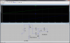
BATT+ and BATT- are 2 x Li-Ion cells in series
VOUT is the output from a 20A variable power module that can output from 0.6V to 6.6V
VSENSE goes to a 10 bit 3.3V ADC so a divider is used to bring the maximum 8.4V supply voltage down to 3.3V and is used to detect the battery level.
OSENSE goes to a 10 bit 3.3V ADC so a divider is used to bring the maximum 6.6V output down to 3.3V and is used to detect the output voltage.
ISENSE goes to a 10 bit 3.3V ADC and is used to detect the voltage across the load. The opamp amplifies the difference between the VOUT and the voltage after the shunt by a factor of 11. The output is then put through a divider to bring it down to the 3.3V ADC tolerance.
RLOAD is a removable and replaceable load that can vary from 0.2 ohms to 5 ohms although I'm never going to use anything much lower than 1 ohm.
The microcontroller can then use the following to work out the data (some degree of calibration will be required to fine tune)
VOUT = OSENSE / 155.2 (Output voltage of module)
BATT = VSENSE / 121.9 (Battery level)
ASHUNTV = ISENSE / 155.2 (Amplified voltage drop)
SHUNTV = (VOUT - ASHUNTV) / 11 (Voltage across the shunt)
IOUT = SHUNTV / 0.01 (Output current)
RLOAD = (VOUT-SHUNTV) / IOUT (Resistance of RLOAD)
Many thanks
M
BATT+ and BATT- are 2 x Li-Ion cells in series
VOUT is the output from a 20A variable power module that can output from 0.6V to 6.6V
VSENSE goes to a 10 bit 3.3V ADC so a divider is used to bring the maximum 8.4V supply voltage down to 3.3V and is used to detect the battery level.
OSENSE goes to a 10 bit 3.3V ADC so a divider is used to bring the maximum 6.6V output down to 3.3V and is used to detect the output voltage.
ISENSE goes to a 10 bit 3.3V ADC and is used to detect the voltage across the load. The opamp amplifies the difference between the VOUT and the voltage after the shunt by a factor of 11. The output is then put through a divider to bring it down to the 3.3V ADC tolerance.
RLOAD is a removable and replaceable load that can vary from 0.2 ohms to 5 ohms although I'm never going to use anything much lower than 1 ohm.
The microcontroller can then use the following to work out the data (some degree of calibration will be required to fine tune)
VOUT = OSENSE / 155.2 (Output voltage of module)
BATT = VSENSE / 121.9 (Battery level)
ASHUNTV = ISENSE / 155.2 (Amplified voltage drop)
SHUNTV = (VOUT - ASHUNTV) / 11 (Voltage across the shunt)
IOUT = SHUNTV / 0.01 (Output current)
RLOAD = (VOUT-SHUNTV) / IOUT (Resistance of RLOAD)


") This is my first venture into current sensing so naturally I'm a little green. I'd have used the simpler low side sensing if the load wasn't chassis earthed, but it is unfortunately,. Thanks for the help.
This is my first venture into current sensing so naturally I'm a little green. I'd have used the simpler low side sensing if the load wasn't chassis earthed, but it is unfortunately,. Thanks for the help.